Operating procedures – Dwyer Series PUF User Manual
Page 40
3: Operating Procedures
36
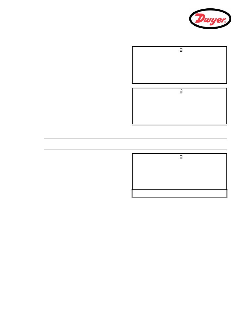
4 to 20 mA Signal scaling
Note: The 4 to 20 mA can be set to represent a particular flow range. It is also possible to enter a negative figure
for the minimum output and this would enable a reverse flow to be monitored.
10. Select
Output mA for error and enter a value (default is 22 mA) that you want the 4 to 20 mA output to
produce in the event of an error (e.g. if the flow-rate is outside the set range).
11. Upon completion press the
ENTER key to return to the FLOW READING screen.
3.
Connect a calibrated ammeter to the 4 to 20 mA
output and adjust the
UP/DOWN Scroll keys
(Coarse) and
LEFT/RIGHT Scroll keys 5 & 6
(fine) until the output is exactly 4.0 mA.
The DAC should indicate approximately 8000.
4.
Press the
ENTER key when done.
CALIBRATE 4mA
DD-MM-YY HH:MM:SS
Adjust the output current to 4mA
Use
UV
to set, 5/6 to trim
DAC Value: 8000
Press
when done
5.
With the meter still connected to the 4 to 20 mA
output adjust the Scroll keys to obtain an output
of exactly 20 mA.
The DAC should indicate approximately 40000.
6.
Press the
ENTER key when done.
CALIBRATE 20mA
DD-MM-YY HH:MM:SS
Adjust the output current to 20mA
Use
UV
to set, 5/6 to trim
DAC Value: 40000
Press
when done
7.
With the instrument operating in the
FLOW
READING mode, press the 4-20mA function key.
This will access the
4-20mA OUTPUT screen.
8.
Select
Flow at max. output and enter a
value of the flow rate that you want to associate
with a 20 mA output.
9.
Select
Flow at min. output and enter a
value of the flow rate that you want to associate
with a 4 mA output. This could be ‘0’.
4-20 mA OUTPUT
DD-MM-YY HH:MM:SS
4-20 mA O/P is ON
Qxx.xx%
mA Output Reading : 0.00
Output Range : 4-20
Units : gal/min
Flow at max. output : 0.00
Flow at min. output : 0.00
Output mA for error : 22.00
Exit