4 adjusting the roughness factor, Ctor – paragraph 3.5.4, Operating procedures – Dwyer Series PUF User Manual
Page 26
3: Operating Procedures
22
3.5.4 Adjusting the roughness factor
The roughness factor compensates for the condition of the internal pipe wall, as a rough surface will cause
turbulence and affects the flow profile of the liquid. In most situations it is not possible to inspect the pipe
internally and the true condition is not known. In these circumstances experience has shown that the following
values can be used:
4.
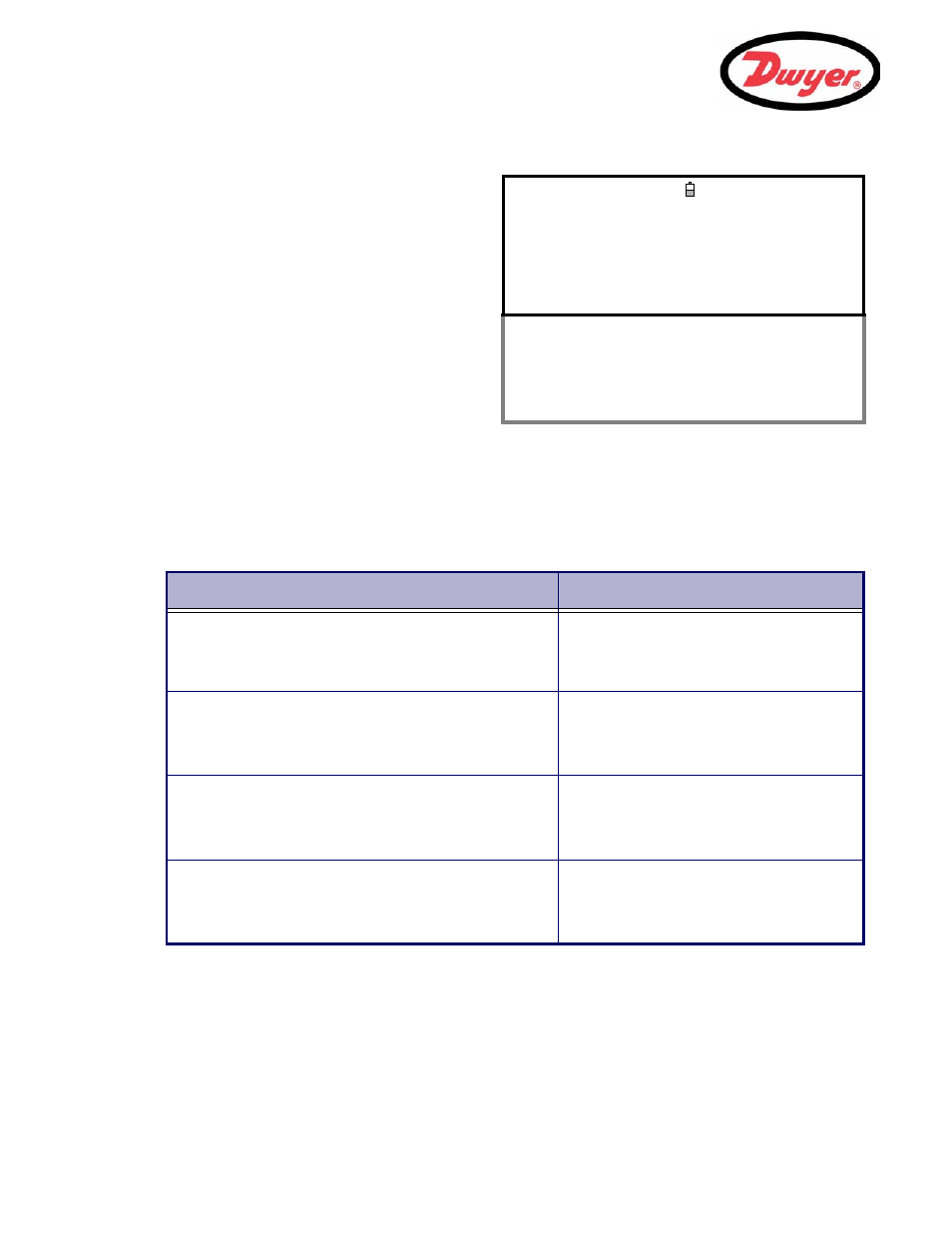
Press the
Options key to access the FLOW
READING OPTION screen shown.
5.
Scroll down and select
Calibration factor.
6.
Change the calibration factor according to the
error calculated in step 3. For example, if the
PUF was reading 1% high then increase the
Calibration factor value by 0.010.
Conversely, if the reading is 1% low then
decrease the calibration factor to 0.990.
7.
Press the
Enter key to apply the change.
8.
Select
Roughness factor or Exit as
required.
FLOW READING OPTION
DD-MM-YY HH:MM:SS
Data review
Zero Cutoff (m/s) : 0.00
Set zero flow (m/s) : 0.00
Damping (secs) : 10
Totalizer : Run
Reset +Total
Reset –Total
Calibration factor : 1.000
Roughness factor : 0.01
Diagnostics
Select Totals : Both
Exit
Pipe Material
Roughness Factor
Non ferrous metal
Glass
Plastics
Light metal
0.01
Drawn steel pipes:
• Fine planed, polished surface
• Plane surface
• Rough planed surface
0.01
Welded steel pipes, new:
• Long usage, cleaned
• Lightly and evenly rusted
• Heavily encrusted
0.1
Cast iron pipes:
• Bitumen lining
• New, without lining
• Rusted / Encrusted
1.0