2 transducer attachment (type ‘a’ & ‘b’), 1 preparation, 2 attaching the transducer holders – Dwyer Series PUF User Manual
Page 12: Installation
2: Installation
8
2.2
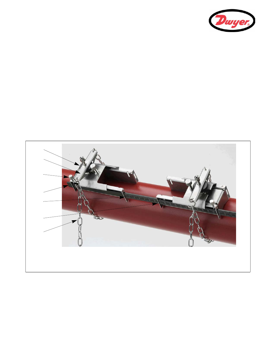
Transducer Attachment (Type ‘A’ & ‘B’)
Type ‘A’ & ‘B’ transducers are fitted to adjustable holders which are secured to the pipe using wrap-around chains
and mechanically connected together by a steel separation bar. The separation bar also acts as a ruler to allow
the distance between the transducers to be accurately set to the value determined by the PUF instrument.
When fitting the transducer holders it is easiest to assemble them onto the separation bar and adjust to the
required separation distance before attaching them to the pipe.
2.2.1 Preparation
1.
Before you attach the transducers you should first ensure that the proposed location satisfies the distance
requirements shown in Figure 2.1, otherwise the resulting accuracy of the flow readings may be affected.
2.
Prepare the pipe by degreasing it and removing any loose material or flaking paint in order to obtain the best
possible surface. A smooth contact between pipe surface and the face of the transducers is an important
factor in achieving a good ultrasound signal strength and therefore maximum accuracy.
2.2.2 Attaching the transducer holders
Figure 2.2 Transducer holders attachment
1.
Slide the separation bar (D) into the front of the left hand holder, align the front edge of the holder with ‘0’ on
the ruler scale (E) and secure it in place by tightening the thumbscrew (C).
2.
Slide the other end of the separation bar into the front of the right hand holder, align the front edge of the
holder to the required separation distance (obtained from the PUF instrument) on the ruler (F), then secure it
in place by tightening the thumbscrew.
A
B
C
D
E
F
G
A: Tensioning thumb-wheel.
B: Tension bar.
C: Separation bar securing
screw.
D: Separation bar.
E: Ruler scale (0).
F: Set Separation distance.
G: Securing chain.