3 fitting the transducers, Installation – Dwyer Series PUF User Manual
Page 13
2: Installation
9
3.
On each holder, attach one end of a securing chain to a hook on the tensioning bar (B), wrap the chain
around the pipe (G) and then attach it to the hook on the other end of the tensioning bar while keeping the
chain as tight as possible.
4.
Rotate the complete transducer holder assembly so that it is approximately 45° with respect to the top of the
pipe. Then tighten the chain by turning the tensioning thumb-wheel (A) on each holder until the assembly is
securely attached to the pipe.
Note: If you are unable to get sufficient tension on the chain to hold the assembly in place, fully slacken the
tensioning thumb-wheel and shorten the effective length of the chain wrapped around the pipe by connecting
the tensioning bar to the next link in the chain, then re-tension.
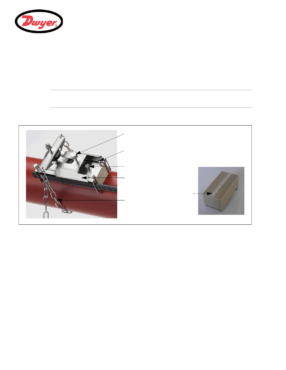
2.2.3 Fitting the transducers
Figure 2.3 Fitting the transducers
1.
Slide the transducer cover plate (A) fully towards the outside of the holder assembly to allow sufficient access
to fit the transducer.
2.
Clean the face of the transducer, removing all traces of dirt and grease.
3.
Apply a
1
/
8
" bead of ultrasonic couplant along the center length of the transducer (E).
4.
Fit the transducer into the holder – ensuring the lugs on the sides of the transducer are correctly located into
the slots on the sides of the transducer holder (B).
5.
Slide the transducer cover plate (A) over the top of the transducer and tighten the thumbscrew (C) finger tight
to secure the transducer in place. When securing the cover plate take care to leave sufficient room around
the transducer connector (D) to connect the cable.
6.
Repeat the above steps for the second transducer.
7.
Connect the transducers to the PUF instrument using the coaxial cables provided. The
RED cable must be
connected to the upstream transducer and the
BLUE cable to the downstream transducer. If you observe a
negative flow, swap the red and blue cables at the sensor end.
A: Transducer cover plate.
B: Transducer locating slot/lug.
C: Transducer cover plate securing screw.
D: Transducer cable connection.
E: Ultrasonic
couplant
application.
G: Securing chain.