Front panel overview, Overview, Feedback control unit – GW Instek SPD-3606 User Manual
Page 7: Ovp setting unit
OVERVIEW
13
CH1/2/3
Controller
The Controller for Channel 1, 2, and 3 takes care of
the interface between SPD-3606 and users. Several
sub-units comprise the Controller, including:
•
Feedback control unit
•
OVP setting unit
•
Fan control unit
Detailed description of each unit follows.
Feedback control
unit
The Feedback control unit receives the control
signal for Voltage/Current output level and the
level feedback signal from the actual output. The
difference between the two signals are amplified
and used as the control signal for the Power stage
to achieve stable output level.
OVP setting unit
The SVR (small variable resistor) sets the
protection point so that the OVP setting unit shuts
down the output when the output Voltage level
exceeds the configured level.
Fan control unit
Using NTC (negative temperature coefficient)
resistor, the Fan control unit changes the control
Voltage for the cooling fan according to the
temperature change, achieving low-noise and
linear speed control.
Tracking
Controller
The Tracking controller controls Channel 2 output
level when in tracking series or parallel mode. In
tracking series mode, Channel2 output Voltage is
controlled by Channel1 output Voltage level. In
tracking parallel mode, Channel2 output Current
is controlled by Channel1 output Current level.
LED Display
The LED display shows the Channel 1/2/3 output
Voltage/Current level. The A/D converter
changes the analog signal coming from each
channel into digital format to be displayed.
SPD-3606 User Manual
14
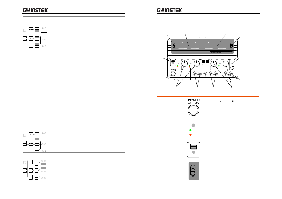
Front Panel Overview
VOLTAGE
VOLTAGE
CURRENT
CURRENT
OVER LOAD
CH3
VOLTAGE
OUTPUT
CH2
CH1
SLAVE
MASTER
TRACKING
INDEP.
SERIES
PARALLEL
C.V.
O.V.P.
SET
C.V.
C.C.
TRIP
C.C.
PAR.
CH2
CH1
CH3
GND
0.1 5V , 3A
0 60V , 3A
0 30V , 6A
0 60V , 3A
0 30V , 6A
ON / OFF
Dual−Range DC Power Supply
CH1
CH3
CH1 / CH3
CH2
60V/3A
30V/6A
SPD-3606
CH2 Meter
Output Range
Switch
CH1/CH3
Meter Switch
CH1/3 Meter
Output
Key
Power
Switch
OVP
Indicator
CH2 Output
Knob
CH2
Indicator
CH2 Output
Terminal
Ground
Terminal
Tracking Mode
Switches
CH3 Overload
Indicator
CH3 Voltage
Knob
CH3 Output
Terminal
CH1 Output
Knob
CH1
Indicator
CH1 Output
Terminal
Power switch
Turns On or Off the main power.
For power up sequence, see page20.
OVP indicator
O.V.P.
SET
TRIP
Turns green during the OVP setup.
Turns red (tripped) when the output
Voltage exceeds the setting. For
OVP details, see page22.
Output Key
OUTPUT
ON / OFF
Turns the output On (green) or Off
(gray), all three channels at once.
Output range
switch
60V/3A
30V/6A
Selects the output range, 60V/3A or
30V/6A.