Recording tables – GW Instek SPD-3606 User Manual
Page 27
PERFORMANCE
VERIFICATION
53
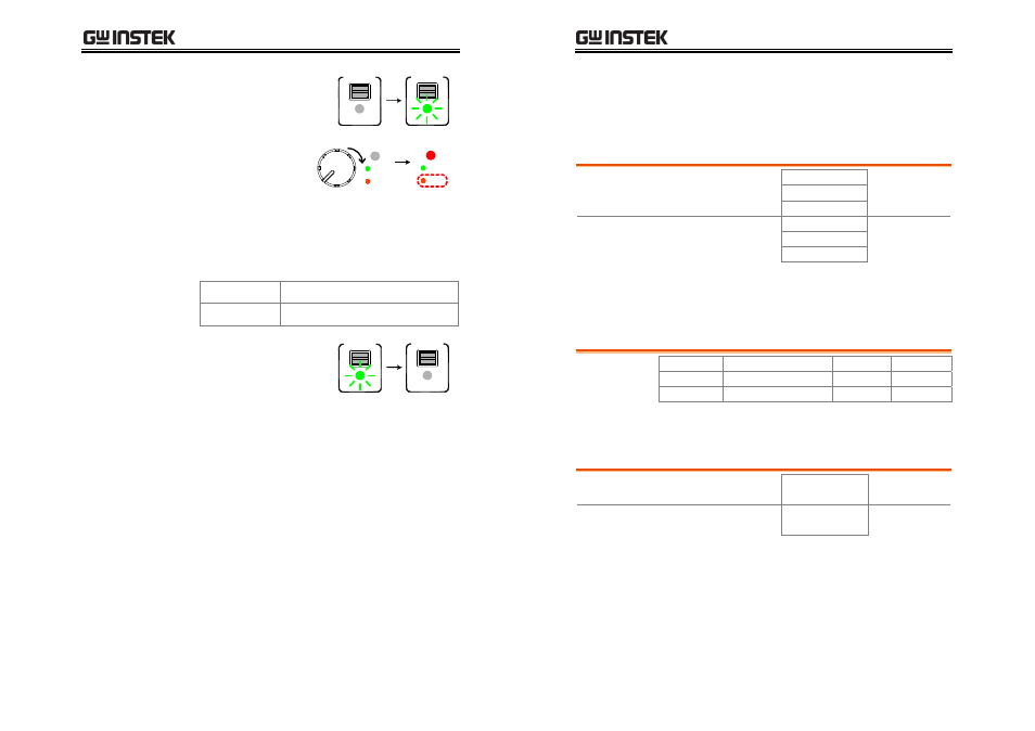
19. Turn On the SPD output.
OUTPUT
ON / OFF
OUTPUT
ON / OFF
20. Slowly turn up the
SPD Voltage knob
until the OVP
indicator turns red
(tripped).
VOLTAGE
O.V.P.
SET
TRIP
O.V.P.
SET
TRIP
Maximum OVP
functionality
21. Record the SPD Voltage meter reading as the
Maximum range OVP functionality. Here is the
acceptance range.
Channel1/2
59.2V ~ 60.8V
Channel3
4.47V ~ 5.53V
22. Turn Off the SPD output.
OUTPUT
ON / OFF
OUTPUT
ON / OFF
23. Repeat step 3 to 22 for Channel2.
24. Repeat step 3 to 22 for Channel3.
SPD-3606 User Manual
54
Recording Tables
Output voltage verification (Minimum/Maximum)
Item
Channel Min. limit
Result
Max. limit
CH1 –30mV
0mV
Minimum
Output Voltage CH2 –30mV
0mV
CH3
0mV
100mV
CH1 61.5V
62.5V
Maximum
Output Voltage CH2 61.5V
62.5V
CH3
5.2V
5.3V
Output voltage verification (Meter accuracy)
Tolerance = ± (0.5%*Multimeter +0.2) V
Channel Multimeter Tolerance SPD
(On) SPD (Off)
Channel1
~
Channel2
~
Channel3
~
Tracking series voltage verification
Item
Channel Min. limit
Result
Max. limit
Tracking Series
Minimum
CH2 0.985V
1.015V
Tracking Series
Maximum
CH2 59.69V
60.31V