Tracking series with common terminal, Common – GW Instek SPD-3606 User Manual
Page 17
OPERATION
33
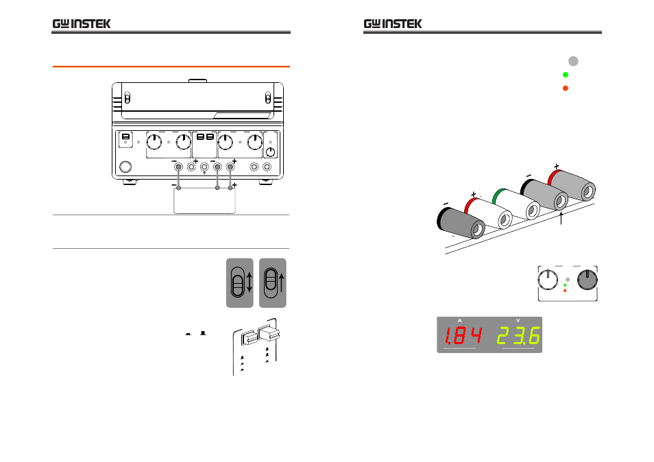
Tracking series with common terminal
Connection
CH2
CH1
LOAD
COM
Output rating
0~60V/0~3A or 0~30V/0~6A for CH1 ~ COM
0~–60V/0~3A or 0~–30V/0~6A for CH2 ~ COM
Setting step
1. Select the output range,
60V(120V)/3A or
30V(60V)/6A. Set the
CH1/CH3 meter switch to
the CH1 position.
60V/3A
30V/6A
CH1
CH3
2. Set the tracking switch
position to Series, + .
TRAC
KING
INDE
P.
SERI
ES
PARA
LLEL
SPD-3606 User Manual
34
3. Set the OVP if necessary. In
tracking series mode, set the
Channel2 (Slave) OVP setting to
the maximum level, so that the
OVP trips if the Channel1
(Master) setting is violated. For
OVP setup details, see page22.
O.V.P.
SET
TRIP
4. Connect the load to the front panel terminals,
channel1+ & channel2−. Use Channel1 (−)
terminal as the common line connection.
CH2
CH1
GND
0 60
V , 3A
0 30
V , 6A
0 60
V , 3A
0 30
V , 6A
Common
5. Set the output Voltage using
the Channel1 (Master)
Voltage knob. Refer to the
Channel1 (Master) meter for
the output setting level.
VOLTAGE
CURRENT
CH1
MASTER
C.V.
C.C.
CH1 / CH3
CH1(+)~COM Voltage = 23.6V in the above case
CH2(–)~COM Voltage = –23.6V in the above case
- GDB-03 (99 pages)
- GLA-1000 Series User Manual (111 pages)
- GLA-1000 Series Quick start guide (20 pages)
- GOS-630FC (20 pages)
- GOS-635G (36 pages)
- GOS-6000 Series (27 pages)
- GOS-6103C (30 pages)
- GOS-6100 Series (30 pages)
- GRS-6000A Series (51 pages)
- GDS-122 Installation Guide (4 pages)
- GDS-122 User Manual (52 pages)
- GDS-2000A series CAN/LIN bus User Manual (18 pages)
- GDS-2000A series Quick start guide for DS2-FGN (6 pages)
- GDS-2000A series Freewave User Manual (26 pages)
- GDS-2000A series Quick start guide for Logic analyzer option (18 pages)
- GDS-2000A series Quick start quide for DS2-LAN (2 pages)
- GDS-2000A series Option User Manual (80 pages)
- GDS-2000A series User Manual (261 pages)
- GDS-2000A series Programming Manual (272 pages)
- GDS-2000A series Single sheet for LA Quick start guide (2 pages)
- GBS-1000 Series Programming Manual (88 pages)
- GBS-1000 Series User Manual (187 pages)
- GDS-1000-U Series firmware upgrade (1 page)
- GDS-1000-U Series Programming Manual (70 pages)
- GDS-1000-U Series Quick start guide (2 pages)
- GDS-1000-U Series User Manual (133 pages)
- GDS-1000A-U Series Programming Manual (88 pages)
- GDS-1000A-U Series Quick start guide (2 pages)
- GDS-1000A-U Series User Manual (148 pages)
- GDS-3000 Series GCP-530/1030 current probe User Manual (40 pages)
- GDS-3000 Series GDP-025/050/100 differential probe User Manual (21 pages)
- GDS-3000 Series DS3-PWR Power analysis manual (37 pages)
- GDS-3000 Series User Manual (209 pages)
- GDS-3000 Series Programming Manual (103 pages)
- GDS-3000 Series DS3-SBD Serial Bus decode (29 pages)
- GDS-3000 Series GKT-100 deskew fixture User Manual (1 page)
- GDS-3000 Series GUG-001, GPIB to USB adapter User Manual (15 pages)
- GDS-300 Series User Manual (188 pages)
- GDS-300 Series Programming Manual (139 pages)
- GDS-300 Series Quick start guide (21 pages)
- GRF-3300 Series Student Manual (26 pages)
- GRF-3300 Series Teacher Manual (26 pages)
- GRF-1300A (124 pages)
- GSP-810 User Manual (40 pages)
- GSP-810 Software Manual (3 pages)