Load cable connection – GW Instek SPD-3606 User Manual
Page 12
SETUP
23
* When setting the OVP for
channel3, select CH3 meter
using the CH1/CH3 meter
switch.
CH1
CH3
5. When finished, slide the
rear panel switch to the
“Normal” position. The
OVP indicator on the front
panel turns Off.
CH3
CH2
CH1
O.V.P. SET
NORMAL
O.V.P.
SET
TRIP
O.V.P.
SET
TRIP
When OVP is
activated....
The OVP activates when one
of channel1/2/3 output
voltage exceeds the OVP
setting. The indicator turns red
(tripped), and the output is
shut Off immediately.
O.V.P.
SET
TRIP
O.V.P.
SET
TRIP
OUTPUT
ON / OFF
OUTPUT
ON / OFF
SPD-3606 User Manual
24
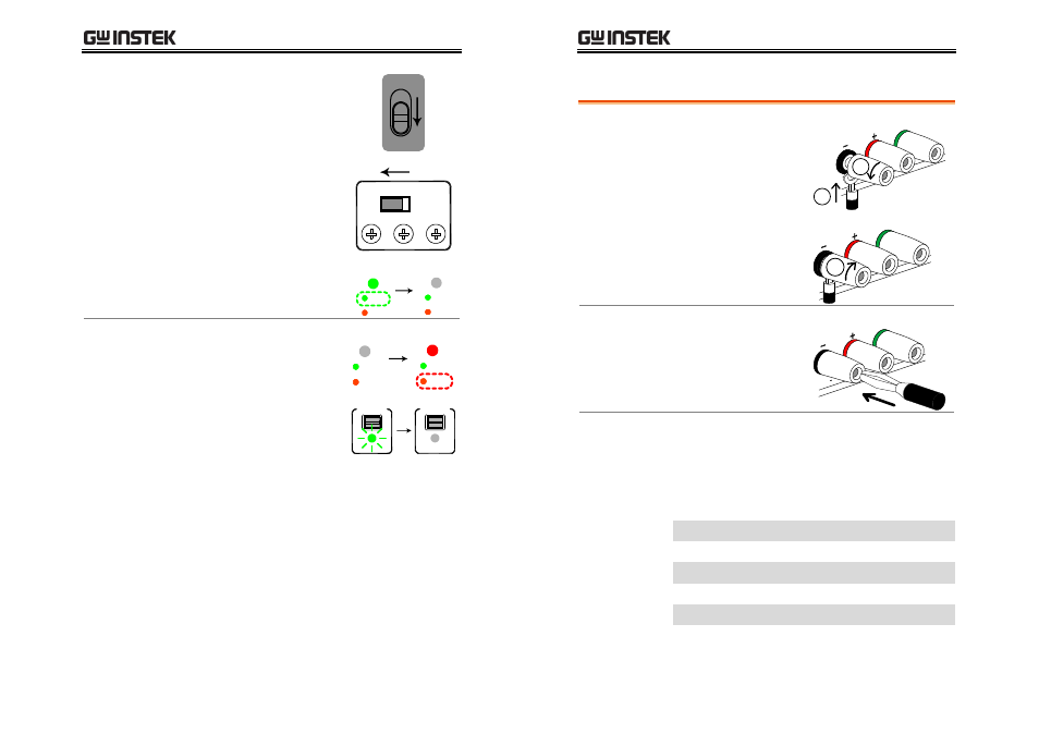
Load Cable Connection
Standard
accessory
(GTL-104)
1. Turn the terminal
counterclockwise and
loose the screw.
2. Insert the cable
terminal.
CH2
GND
0 60
V , 3A
0 30
V , 6A
2
1
3. Turn the terminal
clockwise and tighten
the screw.
CH2
GND
0 60
V , 3A
0 30
V , 6A
3
Banana plug
Insert the plug into the
socket.
CH2
GND
0 60
V , 3A
0 30
V , 6A
Wire type
When using load cables other than the attached,
make sure they have enough current capacity for
minimizing cable loss and load line impedance.
Voltage drop across a wire should not excess 0.5V.
The following list is the wire current rating at
450A/cm
2
.
Wire size (AWG)
Maximum current (A)
20
2.5
18
4
16
6
14
10
12
16