GW Instek SPD-3606 User Manual
Page 19
OPERATION
37
3. Set the OVP if necessary. In
tracking parallel mode, set
the Channel2 (Slave) OVP
setting to the maximum
level, so that the OVP trips if
the Channel1 (Master)
setting is violated. For OVP
setup details, see page22.
O.V.P.
SET
TRIP
4. Connect the load to the front panel terminals,
channel1 +/−.
CH2
CH1
GND
0 60
V , 3A
0 30
V , 6A
0 60
V , 3A
0 30
V , 6A
5. The Channel2 (Slave)
indicator turns red,
indicating Tracking Parallel
(PAR). The CV/CC status of
tracking parallel mode is
displayed in the Channel1
(Master) indicator.
C.V.
C.C.
PAR.
C.V.
C.C.
PAR.
6. Set the output Voltage and
Current using the Channel1
(Master) control knobs.
Channel2 control knobs are
disabled.
VOLTAGE
CURRENT
CH1
MASTER
C.V.
C.C.
SPD-3606 User Manual
38
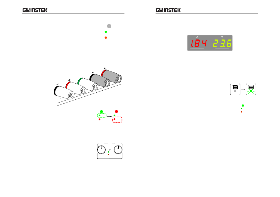
7. Refer to the Channel1 meter for the output
setting level.
CH1 / CH3
Current
level
Double the reading on the
Channel1 meter. In the above
case, the actual output is 1.84 x 2
= 3.68A.
Voltage
level
Channel1 meter reading shows
the actual output Voltage.
8. Press the Output key. The
Output indicator turns
green.
OUTPUT
ON / OFF
OUTPUT
ON / OFF
9. Refer to the Channel1
(Master) indicator for the
CV/CC status.
CH1
MASTER
C.V.
C.C.