Principle of operation, Power supply, Ch3 ch1 – GW Instek SPD-3606 User Manual
Page 6: Display
OVERVIEW
11
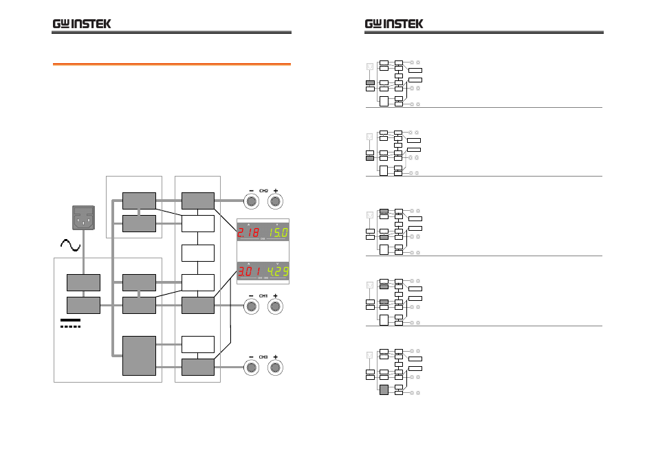
Principle of Operation
Block diagram
Power supply converts the AC mains into DC
Power source for internal units. Channel 1/2/3
control and produce the actual DC output. Display
shows output and OVP level, receiving feedback
from each channel. Internal components are placed
on four printed circuit boards, A ~ D.
Detailed description of each module starts on the
next page.
Power
Supply
PCB A
CH3
CH1
AUX
Power
Controller
Output
Power
Stage
Controller
Output
Power
Stage
CH2
Power
Stage
Output
Controller
AUX
Power
Tracking
Controller
Display
Rectifier/
Doubler
EMI Filter
PCB B
PCB C
PCB D
SPD-3606 User Manual
12
EMI Filter
Other than deleting conduction EMI (electro-
magnetic interference), the EMI unit contains
protective circuits such as Inrush current limit
resistor and Surge absorber. Internal units are
protected under power-up sequence, normal
operation, and AC mains fluctuation.
Rectifier / Doubler
The Rectifier unit converts AC mains into DC
Power source. For 115V±15% AC, double-wave
rectification is used; for 230V±15% AC, full-wave
rectification. An internal selector automatically
switches the rectification circuit accordingly. The
final DC Voltage reaches 240V ~ 370V.
CH1/2 Power
Stage
The Power stage for Channel1 and 2 produce the
outputs using the combination of Half-bridge
converter and Linear regulator. The Half-bridge
converter adopts PWM (pulse-width modulation)
with high frequency switching. The Linear
regulator adjusts the output Voltage down to 0V.
CH1/2 AUX Power
The AUX Power for Channel 1 and 2 produces the
power source for auxiliary devices, such as
analog/digital controller, relay, LED display, and
cooling fan. Altogether four pairs of power source
are generated for different purpose: ±12V, +5V,
and +12V.
CH3 Power Stage
The Power stage for Channel 3 produces both the
channel output and the power source for auxiliary
devices. It uses the combination of Flyback
converter and Linear regulator, carrying lower
efficiency compared to Channel 1 and 2. The
flyback converter also produces ±12V for ICs and
4~8V settable Voltage.