GW Instek SPD-3606 User Manual
Page 26
PERFORMANCE
VERIFICATION
51
Minimum OVP
setting
6. Record the SPD Voltage meter reading as the
Minimum OVP setting accuracy. Here is the
acceptance range.
Channel1/2
≤ 1.0V
Channel3
≤ 0.50V
7. Adjust the OVP setting
terminal until the SPD
meter shows the exact
following value.
CH1
INCREASE
DECREASE
Channel1/2
1.0V
Channel3
0.50V
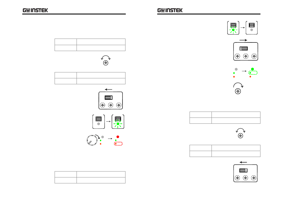
8. Set the OVP setting switch to
the “Normal” position. The
OVP indicator on the front
panel turns Off.
CH3
CH2
CH1
O.V.P. SET
NORMAL
9. Turn On the SPD output.
OUTPUT
ON / OFF
OUTPUT
ON / OFF
10. Slowly turn up the
SPD Voltage knob
until the OVP
indicator turns red
(tripped).
VOLTAGE
O.V.P.
SET
TRIP
O.V.P.
SET
TRIP
Minimum OVP
functionality
11. Record the SPD Voltage meter reading as the
Minimum range OVP functionality. Here is the
acceptance range.
Channel1/2
0.5V ~ 1.5V
Channel3
0.00V ~ 1.00V
SPD-3606 User Manual
52
12. Turn Off the SPD output.
OUTPUT
ON / OFF
OUTPUT
ON / OFF
13. Set the OVP setting switch to
the “O.V.P. SET” position.
CH3
CH2
CH1
O.V.P. SET
NORMAL
14. The O.V.P. indicator on the
front panel turns green.
O.V.P.
SET
TRIP
O.V.P.
SET
TRIP
15. Turn up the OVP setting
terminal to maximum.
CH1
INCREASE
Maximum OVP
setting
16. Record the SPD Voltage meter reading as the
Maximum OVP setting accuracy. Here is the
acceptance range.
Channel1/2
65.0 ~ 68.0V
Channel3
6.00 ~ 7.00V
17. Adjust the OVP setting
terminal until the SPD
meter shows the exact
following value.
CH1
INCREASE
DECREASE
Channel1/2
60.0V
Channel3
5.0V
18. Set the OVP setting switch to
the “Normal” position. The
OVP indicator on the front
panel turns Off.
CH3
CH2
CH1
O.V.P. SET
NORMAL