Tracking series voltage verification – GW Instek SPD-3606 User Manual
Page 23
PERFORMANCE
VERIFICATION
45
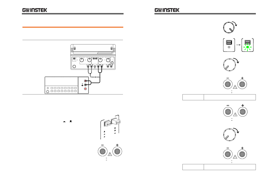
Tracking Series Voltage Verification
Check item
•
Minimum output Voltage accuracy
•
Maximum output Voltage accuracy
Connection
Digital Multimeter
SPD-3606
V
A
Verification step
1. Set the SPD panel according to the Default setting
list, page41, except for the tracking switch (see
below).
2. Set the tracking switch position
to Series, + .
TRAC
KING
INDE
P.
SERI
ES
PARA
LLEL
3. Connect SPD Channel 1 and
Digital Multimeter Voltage
terminal.
CH1
0 60V , 3A
0 30V , 6A
4. Power up SPD and Digital Multimeter.
SPD-3606 User Manual
46
5. Turn up the SPD Current
knob, both Channel1 and
Channel2, to the maximum.
CURRENT
6. Turn On the SPD output.
OUTPUT
ON / OFF
OUTPUT
ON / OFF
7. Turn up the SPD Channel1
Voltage knob until the
Multimeter reading shows
1.000V.
VOLTAGE
(1.000V)
Minimum
tracking series
output voltage
8. Connect the Multimeter to
SPD Channel2 and record
the reading. Here is the
acceptance range.
CH2
0 60V , 3A
0 30V , 6A
Channel2
0.985V ~ 1.015V
9. Connect Digital Multimeter
back to SPD Channel1.
CH1
0 60V , 3A
0 30V , 6A
10. Turn up the SPD Channel1
Voltage knob until the
Multimeter reading shows
60.00V.
VOLTAGE
(60.00V)
Maximum
tracking series
output voltage
11. Connect the Multimeter to
SPD Channel2 and record
the reading. Here is the
acceptance range.
CH2
0 60V , 3A
0 30V , 6A
Channel2
59.69V ~ 60.31V