Warning – Hired-Hand Evolution 4000 Control System User Manual
Page 60
Part No. 4801-5338 Rev 01-10
Evolution 4000
60 of 86
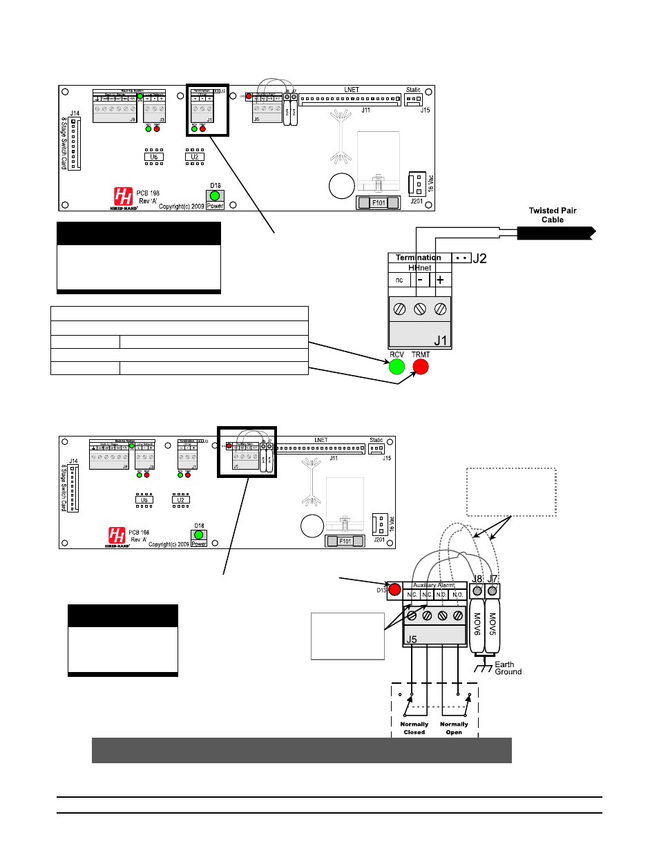
9.7
Connecting HHnet PC Network to Evolution
4000
9.8
Connecting Alarm Device to Evolution
4000
WARNING!
LOW VOLTAGE!
Keep Separate From
High Voltage Wires!
WARNING!
LOW VOLTAGE!
Keep Separate From
High Voltage Wires!
Inset A
PCB 198
Inset A
NOTE: The internal wiring shows the condition of the relay during normal conditions
(no alarm present). During an alarm condition, the contact positions will be reversed.
N.O. for
Parallel Alarm
connection
N.C. for
Series Alarm
Connection
Internal Circuit
Board Auxiliary
Alarm Relay
Inset A
On-Board Surge
Arrestors for
use with either
N.O. or N.C.
side.
Inset A
HHnet: Light Emitting Diode (LED) Indicators
D7 - RCV (Green LED)
GREEN HHnet Receiving Data
D8 – TRMT (Red LED)
RED HHnet Transmitting Data
PCB 198
Red LED ON -
Controller has an
Alarm Condition.
- Polar Cool: Portable Evaporative Cooling System (22 pages)
- Polar Cool: External Control Box (4 pages)
- Polar Cool: Pump & Float Replacement (2 pages)
- Polar Cool: PUMP REPLACEMENT (4 pages)
- Polar Cool: Wall Mount Kit (4 pages)
- Unitized Mega Cool (68 pages)
- Unitized Mega Cool: Square Bottom (63 pages)
- Mega-Cool: Square Reservoir (24 pages)
- Mega-Cool rev 6-09 (46 pages)
- Mega-Cool: Mega-Cool Pad Extender Kit (5 pages)
- Mega-Cool: Float Valve Replacement (1 page)
- Mega-Cool: Float Valve (Topaz) Replacement (1 page)
- Mega-Cool: In-Line Pump Motor Replacement (2 pages)
- Var-O-Matic (2 pages)
- System 1000 Power Vent (31 pages)
- System 1000 Power Vent (13 pages)
- System 500 Programs (Conventional Model) (5 pages)
- System 100 Variable Speed Controller (7 pages)
- System 500 Programs (Tunnel Model) (7 pages)
- System 1000 Power Curtain (17 pages)
- System 2000 AUTO TEMP (10 pages)
- System 2001 Power Curtain Controller (43 pages)
- System 500 Power Curtain Controller (31 pages)
- System 1000 Power Curtain Eight Stage Controller (34 pages)
- ICS-500 Environmental Controller (34 pages)
- Pressure Transducer Changeout (1 page)
- HH Software: HH.Net Router/Repeater (8 pages)
- HH Software: 900SS Wireless Network (10 pages)
- HH Software: Farm Manager (22 pages)
- HH Software: Data Shuttle Launch Pad (25 pages)
- Sens-O-Matic (Feed Hopper Switch) (2 pages)
- Manual Light Dimmer (2 pages)
- Electro Mechanical Controls (Relay-Switches): PHOTOHELIC POWER VENT (10 pages)
- Electro Mechanical Controls (Relay-Switches): PT Controller (9 pages)
- Electro Mechanical Controls (Relay-Switches): PC-DB Curtain Controller with DIF (6 pages)
- Electro Mechanical Controls (Relay-Switches): PC-DB Curtain Controller with Timer Override (7 pages)
- Electro Mechanical Controls (Relay-Switches): Photohelic Gauge (1 page)
- Feed Management System (15 pages)
- Contactor Control System (CCS): 4, 8, or 12 Stage (19 pages)
- Contactor Control System (CCS): Triple Pole 16-Stage (7 pages)
- Contactor Control System (CCS): Vent Machine Override 3 Wire PowerTrak (1 page)
- Evolution Series 1200: Variable Output With Override Pot (14 pages)
- Evolution Series 1200: Variable Output (12 pages)
- Evolution Series 1200 (64 pages)