1 current conditions – main system – Hired-Hand Evolution 4000 Control System User Manual
Page 14
Part No. 4801-5338 Rev 01-10
Evolution 4000
14 of 86
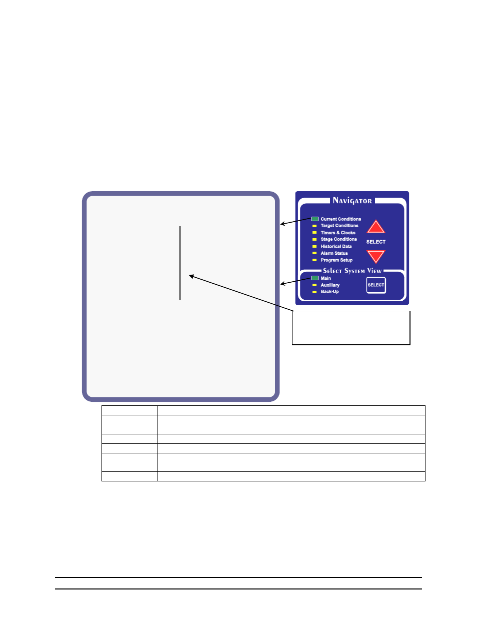
Tue 15 Sep 2009 10:45a
(1) Growout Day: 258
(2) Ventilation Mode: Minimum
(3) Room Temp: 71.4°
Target:
70.0°
(4) Pressure: 0.00 wc Target:
0.04 wc
(5) Humidity:
0%
Target <
60%
(6) Outside: 77.0° (7)
Enclosure:
95.0°
(8)Water Consumption
(9) Feed Levels
1. 240
(10/hr) 1. 11.2ft
( 60%)
2. 280
(10/hr) 2. 5.0ft
( 23%)
PAGE for Details
(10)
√ Sensor enabled
* Sensor in Room Temp
√ * Sensor 1: 71.6°
√ * Sensor 2: 71.2°
√ * Sensor 3: 71.4°
Sensor 4:---.-°
Sensor 5:---.-°
Sensor 6:---.-°
Sensor 7:---.-°
Sensor 8:---.-°
NOTE: In this manual, Reference
numbers refer to descriptions given in
text. These numbers do not appear on
display.
6.1
Current Conditions – MAIN SYSTEM
The current environmental conditions of the building are shown here. Below is a table describing the
variables that can appear in the Current Conditions status screen.
The numbers in brackets e.g. (1) refer to the descriptions below the sample screen displays.
(1) Growout Day – The current day in the growout period. The Current Conditions LED on the Navigator
panel will blink if the growout day is later then the current date.
(2) Vent Mode – Indicates the current ventilation mode: either Minimum, Natural, Power, Transition or
Tunnel.
(3) Room Temp – The average temperature of the sensors for display. Target-– Target Temperature.
(4) Pressure – The current atmospheric pressure internal to the building. Target-– Target Pressure.
(5) Humidity – The percent of water vapor of the air inside the building.
(6) Outside (Temperature) – The outside temperature as indicated by the outside sensor.
(7) Enclosure (Temperature) – The temperature inside the controller.
VENT MODE
Definition
Minimum
Heat stages or timer fans operating. None of the negative stages are on because of
temperature.
Natural
The main curtains are open.
Power
The curtains are up and there are negative fans on because of temperature.
Transition
The control is transitioning into tunnel ventilation from either power or natural
ventilation. The control is making the adjustments needed to go into tunnel.
Tunnel
The tunnel signal has been activated and the system has entered into tunnel.
(8) Water Consumption – Water consumed for the current day; The total for the day is listed first then
the units per hour is shown inside ( ). Two water meters may be monitored
(Water Meter 1 & Meter 2).
(9) Feed Level – The Feed level is shown in number of feet from the bottom first then the percentage of
feed remaining in the feed bin is shown inside ( ). Two feed bins may be monitored (Bin
#1 & Bin #2).
(10) Sensor 1 through 8 – The current temperature read by each sensor.