Hired-Hand Evolution 4000 Control System User Manual
Page 26
Part No. 4801-5338 Rev 01-10
Evolution 4000
26 of 86
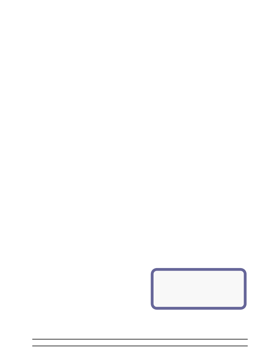
(1)High Temperature Alarm Details
(2)Alarm On/Off = Off
(3)High Temperature Limit = 81.5°
(4)Increase Limit In Tunnel = +2.0
(5)Last Alarm Statistics:
(6)Date: 02/12 (6)Time: 1:09p
(7)Cause: Sensor 1
(1) High Temperature Limit & Status - The high temperature setting at which the alarm relay will activate.
See Section 6.6.1.
(2) Low Temperature Limit & Status - The low temperature setting at which the alarm relay will activate.
See Section 6.6.2.
(3) Cycle Pressure Limit & Status - The pressure setting at which the alarm relay will activate provided the
pressure differential is not seen during the timer period.
(4) High Pressure Limit & Status - The High Pressure alarm will send a signal to your existing alarm system
when the pressure exceeds the High Pressure Setpoint for greater than 45 seconds. (High Negative
Pressure) This alarm warns if the vents did not open for some reason (Automatically enabled during
Tunnel).
(5) Low Pressure Limit & Status – When the Low Pressure alarm is enabled, it becomes a constant pressure
alarm. It will send a signal when pressure drops below the Low Pressure setpoint at any time for greater
than 45 seconds. Setting the Low Pressure alarm setpoint to "OFF" prevents the alarm from sounding.
(6) High Rate - High water usage rate. Alarm if units per hour exceed. One or two water meters (#1 or #2) can
be monitored.
(7) Low Rate - Low water usage rate. Alarm if units per hour drop below. One or two water meters (#1 or #2)
can be monitored.
NOTE: Low Alarm is disabled when lights are off.
(8) Auger Run1 - Alarm if continuous runtime of feed line #1 exceeds selected time limit.
(9) Auger Run2 - Alarm if continuous runtime of feed line #2 exceed selected time limit.
(10) Tunnel Vent - The Tunnel alarm will send a signal if for some reason the controller is unable to enter
tunnel. See Section 6.6.3.
(11) Growout Day - Status & last error (Warning only).
(12) Local Network - Status & last error.
(13) Back-Up Limits - Status & last error.
(14) Sensor 1 through 8 Limit & Status - If the sensor is disabled, this field will show “off”. If the sensor is
enabled, this field will show “OK” if the sensor is functioning properly or “fail” if the sensor is not properly
reporting the temperature. Check wiring for damage or bad connection.
NOTE: This is the status of the alarms. Once an error has occurred the LED for Alarm Status will start
blinking. Use the Navigator arrows to move down to Alarm Status. You will see what has failed. For a
detail of what caused the failure navigate down to highlight the alarm and press enter. This will give a
detail of what caused it and when it happened. High Temp, Low Temp, and Tunnel Vent have an additional
detail screen viewable by scrolling down and highlighting the desired alarm and pressing enter.
(15) Outside -If the sensor is disabled, this field will show “off”. If the sensor is enabled, this field will show
“OK” if the sensor is functioning properly or “fail” if the sensor is not properly reporting the temperature.
Check wiring for damage or bad connection.
6.6.1 High Temperature Alarm Details
The High Temperature Alarm Details lists the settings for the alarm and the last time the alarm was
sounded and the cause of the alarm.
(1) High Temperature Alarm Details – Identifies
the following information:
(2) Alarm On/Off – The status of the alarm is On or
Off.
(3) High Temperature Limit – The current
temperature setting of the High Temperature
alarm.
(4) Increase Limit In Tunnel – Increase high temperature limit during tunnel mode by this number.
(5) Last Alarm Statistics – Identifies the date, time and cause of the last alarm.
(6) Date & Time – The date and time of the last alarm. Date is given as Month/Day.
(7) Cause – Displays the reading of the high temperature that caused the alarm.