Davey Speedman Dual Pump Variable Speed Pump Control System User Manual
Page 28
28
Standby Boost / Standby Flow Min
The Speedman uses one of three methods to determine if there is “no flow”.
The options detailed below are selected via the “Standby Test” screen, which
is in the CONFIGURE menu. Each test is only carried out if there is 1 pump
running, not at maximum speed and the system pressure is at or above the Set Point.
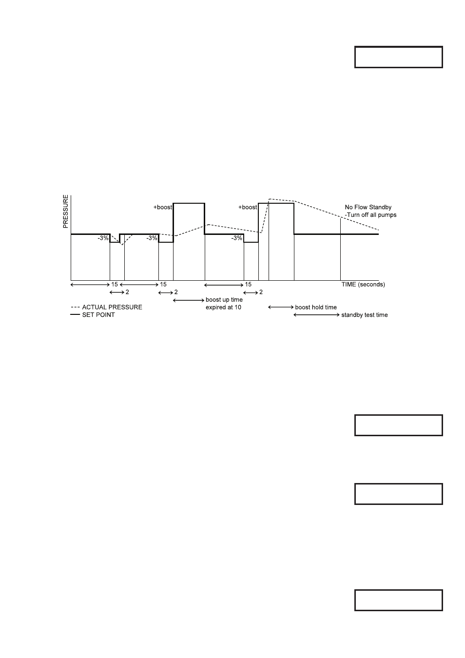
Boost: The Speedman tests for “No Flow” by boosting the system pressure to a new pressure, typically 5%
higher than the set pressure (“Standby Boost”) for a period of time (“Boost Hold Time”) and then checks
the system pressure response over a period of time (“Standby Test Time”). The “Standby Boost” pressure
sets the amount the Set Point pressure is boosted by. The time that it takes to drop back to the Set Point is
compared to the Standby Test time.
*** NOTE *** If the time to return to “Set Point” is less than the “Standby Test” the system continues to
operate.
If the system pressure does not drop to the set point over the test time, the Speedman assumes there is “NO
FLOW” and will pause operation until the cut in pressure point wakes the Speedman to start up again.
Flow Switch: If a Speedman input is programmed to “No Flow”. The flow switch is connected to the selected
Speedman input and when activated the Speedman will turn off the pump after a period
nominated by the standby test time. In this mode both the “Standby Boost” and “Standby Flow/
Sec” screens will be hidden.
Flow Rate: If a flow meter is connected to an analogue or a pulsed input and
set up properly and the flow rate is below the nominated amount in this
menu for the period of the standby test time the system will placed in
standby mode.In this mode the “Standby Flow Min” screen will be visible
& “Standby Boost” will be hidden.
Error Correction (Integral Time)
The error correction time is the time taken to convert a constant error of 1% to
a 1% change on the output. The error correction component is proportional to
the tracking error and increases linearly with time. It is useful when trying to
close the gap on small errors that cannot be eliminated through the use of the response rate alone.
It is expressed as a percentage ranging from Off, 0.1 - 100.0. Off will disable this part of the PID equation.
The current pressure reading is also displayed to assist while tuning – Shown above as “nn”
Overshoot Elimination (Derivative Gain)
The overshoot elimination gain provides a damping effect to eliminate system
oscillation & to minimize overshoot.
It is expressed as a percentage ranging from Off, 0.01 – 50.00. Off will disable
this part of the PID equation.
The current pressure reading is also displayed to assist while tuning – Shown above as “nn”
In this mode the “Standby Boost” screen will be visible & “Standby Flow/Sec” will be hidden.
Standby Boost
XXX
Standby Flow Min
XXXX /min
Error Correct (1)
XXX.X secs (nn)
OvershootElim (D)
XX.XX % (nn)