Davey Speedman Dual Pump Variable Speed Pump Control System User Manual
Page 11
11
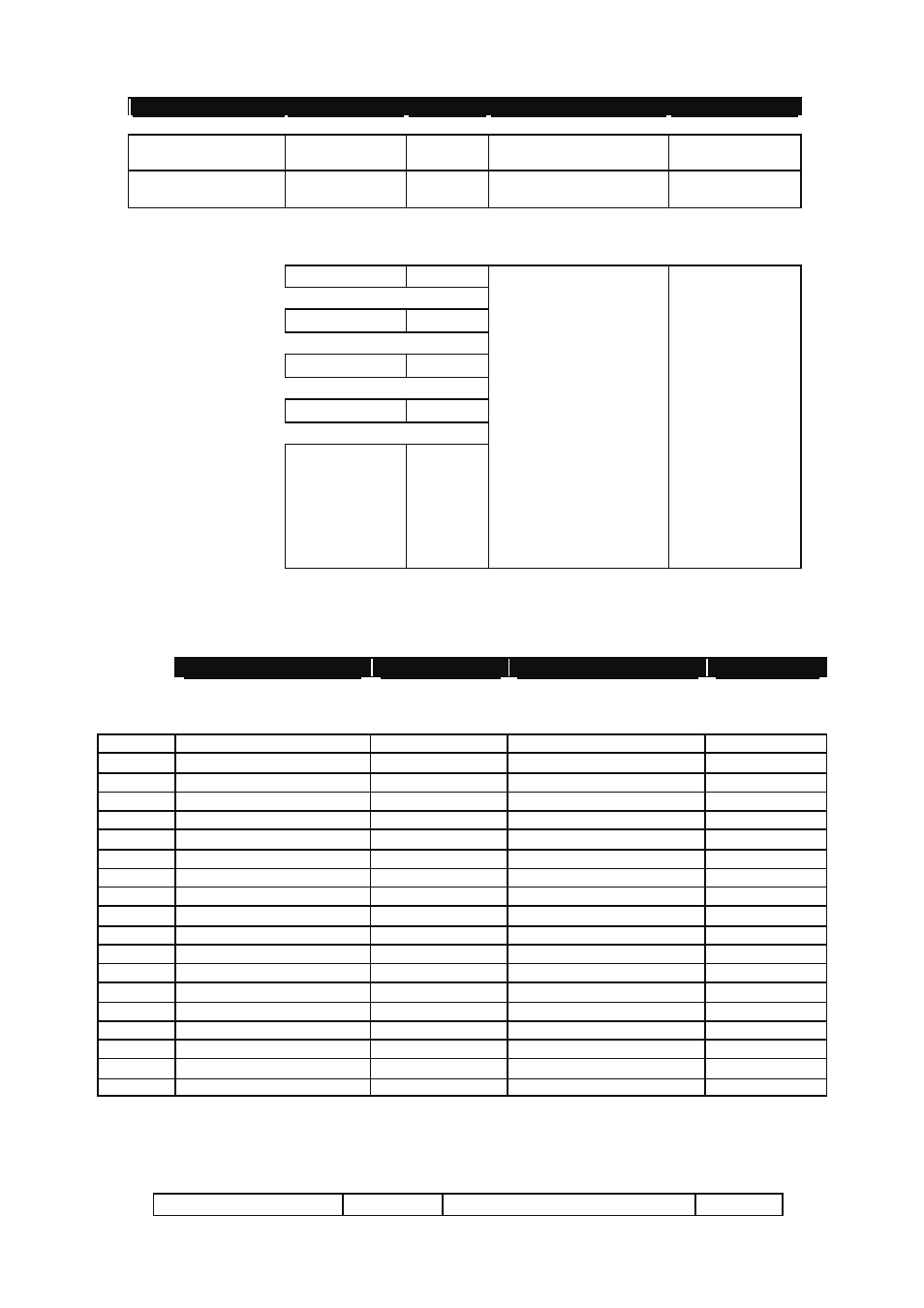
The Speedman controller has menus to allow the system to be tuned.
These menus are listed below and explained in detail later in this manual.
If “RTC ERROR” is displayed at any time, it indicates that the real time clock had not been set when the fault occurred.
To set the clock, go to the “Configure” menu and sub menu “Set Time/Date”
*
These menus are related to other settings. They are not visible unless relevant settings are enabled
!
These menus may be hidden depending on the number of configured pumps.
Main Menu
Sub Menu
Units
Range
Defaults
Set Point &
Actual Pressure
number
0 - 9999
0 - 9999
Display only
Flow Rate/ min &
VSD Speed
number
0 - 9999
0 - 100
Display only
FAULT HISTORY
F1
message
Display only
F2
message
F3
message
F4
message
F5
message
Type/Time/Date
AND
Low Press Shutdown,
High Press Shutdown,
No Flow Shutdown,
VSD Fault,
Pump 1 to 6 Fault,
Pump 1 to 6 Protection,
High Temperature,
Auto Reboot,
Power Failure,
Power glitch,
Analog1 Error,
Analog2 Error,
AnComms Fault
Sub Menu
Units
Range
Defaults
PUMP DATA LOG
Flow Total
Unitless
0 - 9999999
display
Average Flow Rate
/Sec
0 - 9999
display
Average Pressure
Unitless
0 - 9999
display
Highest Pressure
Unitless
0 – 9999
display
Hours Run 1
hours
0 - 65535
display
!
Hours Run 2
hours
0 - 65535
display
Pump Starts 1
number
0 - 65535
display
!*
Pump Starts 2
number
0 - 65535
display
Pump Starts Last Hr
number
0 - 65535
display
Analogue Input 1
%
Disabled, 0.00 - 100.00
display
*
Analogue Input 2
%
Disabled, 0.00 - 100.00
display
*
Analogue Output 1
%
0.00 - 100.00
display
*
Analogue Output 2
%
0.00 - 100.00
display
*
Digital Input State M
1 - 8
X for Active
display
*
Digital Output State
1 - 2
X for Active
display
*
PID Error
%
0.00 - 100.00
display
Current & maximum retry
number
0 – 50 0 – 50
display
*
Temperature
degrees C
0 - 999
display
Modbus monitor
Rx, Tx, Err
0-9999 0-9999 0-9999
display
Access Code
Access Code
number
0 - 250
0