4 wiring for contact output, 1 cable specifications, 2 wiring procedure – Yokogawa Integral Oxygen Analyzer ZR202 User Manual
Page 62: 5 wiring for contact input, Wiring for contact output -5 5.4.1, Cable specifications -5, Wiring procedure -5, Wiring for contact input -5 5.5.1
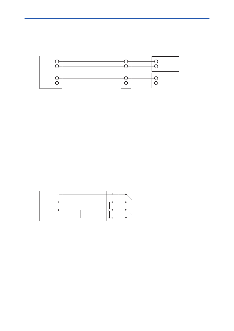
<5. Wiring>
5-5
IM 11M12A01-04E
5.4 Wiring for Contact Output
The equipment can output a maximum of two contact signals. These contact outputs can be used for
different applications such as a low alarm or high alarm.
Do the contact output wiring according to the following requirements.
DO-1
DO-1
DO-2
DO-2
F5.6E.ai
#2 Output
Analyzer
Terminal box
Annunciator or the like
#1 Output
Figure 5.6
Contact Output Wiring
5.4.1 Cable Specifications
The number of cores varies depending on the number of contacts used.
5.4.2 Wiring Procedure
(1) M4 screws are used for the terminals. Use crimp-on terminals appropriate for M4 terminal
screws for cable connections.
(2) The contact output relays are rated 30 V DC 3A, 250 V AC 3A. Connect a load (e.g. pilot lamp
and annunciator) within these limits.
5.5 Wiring for Contact Input
The converter can execute specified function when receiving contact signals.
To use these contact signals, proceed wiring as follows:
Converter
Terminal box
DI-1
DI-C
DI-2
Contact input 1
Contact input 2
F5.7E.ai
Figure 5.14
Contact Input Wiring
5.5.1 Cable Specifications
Use a 2-core or 3-core cable for this wiring. Depending on the number of input(s), determine which
cable to use.