Yokogawa Integral Oxygen Analyzer ZR202 User Manual
Page 55
<4. Piping>
4-6
IM 11M12A01-04E
4.4 Piping for the Oxygen Analyzer with Pressure
Compensation
ZR202G-----P Oxygen Analyzer with pressure compensation may be used in System 2 and
System 3.
Use this style analyzer whenever the furnace pressure exceeds 5 kPa (see Note). Even if the furnace
pressure is high, the detector can measure by adjusting pressure of the probe with the furnace
pressure using instrument air. The inside pressure of the probe will be kept identical to the furnace
pressure by feeding instrument air at higher pressure than that in the furnace.
NOTE
The process gas pressure should not be subjected to rapid changes.
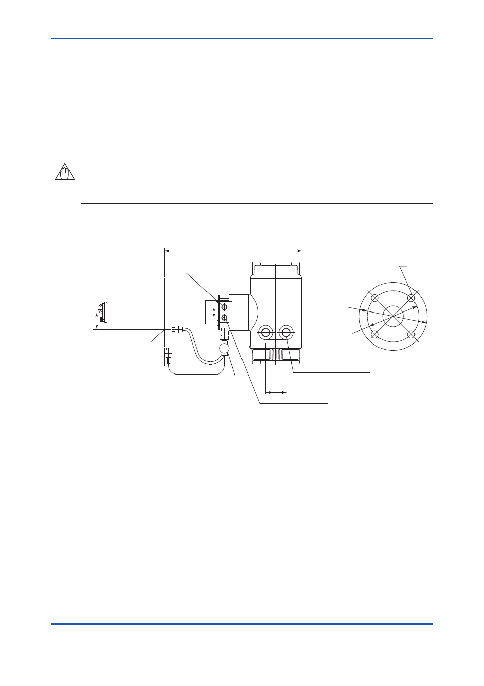
Unit: mm
The detector with pressure compensation is illustrated in Figure 4.12.
49
342±4
25
F4.12E.ai
ØB
ØA
C
*1
*1
*1
*1
*1
*1: Dimension may vary depending on the detector type.
Ensure that the flange gasket does not block off the reference gas outlet.
Where necessary, make a notch on the flange
Rc 1/4 or 1/4 NPT
(Reference gas inlet)
4-G1/2, 2-1/2 NPT or the like
(Wiring connection)
Rc1/4 or 1/4NPT
(Calibration gas inlet)
Stop valve
Reference gas outlet
Flange
PIPING
PIPING
Figure 4.12
Oxygen Analyzer with Pressure Compensation
Ensure that the furnace gas does not flow into the probe.
Valve operation
1. For safety, stop the furnace that the detector is to be installed in. If furnace internal pressure is
high, this is especially dangerous.
2. Before starting instrument air flow, completely shut the stop valve in front of the reference gas
outlet.
3. Check that the reference gas outlet is not blocked by a flange gasket or the like.