Yokogawa Integral Oxygen Analyzer ZR202 User Manual
Page 146
<12. Troubleshooting>
12-7
IM 11M12A01-04E
In addition, if an error occurs in calibration even after the cell assembly is replaced, the influence of
sample gas flow may be suspected. Do not let the sample gas flow toward the tip of the detector
probe, for example, by changing the mounting position of the detector.
12.2.2.5
Alarm 10: Cold Junction Temperature Alarm
The equipment incorporates a temperature sensor. An alarm is issued when the sensor temperature
exceeds 85°C. If internal temperature of this equipment exceeds 85°C, the electronics may fail.
This equipment can be used at ambient temperatures up to 55°C. If the ambient temperatures may
exceed the limits, take appropriate measures such as applying heat insulating material to the furnace
walls, and adding a sun shield to keep out direct sunlight.
If this alarm occurs even when the ambient temperature is under 55°C, the electronics may be
defective. Contact your local Yokogawa service or sales representative.
12.2.2.6
Alarm 11: Thermocouple Voltage Alarm
This alarm is generated when the emf (voltage) of thermocouple falls below -5 mV (about -170°C) or
exceeds 42.1 mV (about 1020°C).
(1) A failure of the thermocouple at the detector occurred.
(2) A failure of the electrical circuits occurred.
(1) Turn off the power to the analyzer.
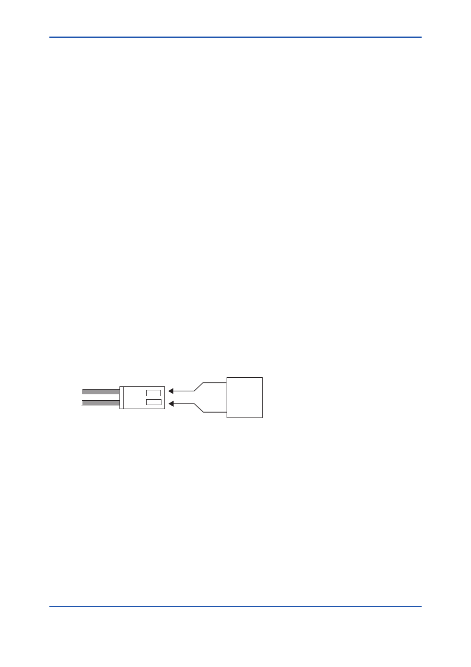
(2) Remove the probe from the analyzer. Also remove all the connectors between the converter
and probe. Measure the resistance of the heater wire (yellow wire) from the probe as indicated
in Figure 12.5. The heater assembly is normal if the resistance is lower than about 90Ω. If the
resistance is higher than that value, the heater assembly may be defective. In this case, replace
the heater assembly (refer to Section 11.1.3, “Replacement of the Heater Assembly”).
F12.2E.ai
Multimeter
(Ω)
Heater wire
Figure 12.5
(3) Next, check the resistance of the thermocouple from the probe. Use a multimeter to measure the
thermocouple resistance between terminal 3 (red cable connected) and terminal 4 (white cable
connected) as indicated in Figure 12.6.
The thermocouple is normal if the resistance is 5Ω or less. If the value is higher than 5Ω, the
thermocouple wire may be broken or about to break. In this case, replace the heater assembly (refer
to Section 11.1.3, “Replacement of the Heater Assembly”).