3 mounting of cable gland, 2 wiring for analog output, 1 cable specifications – Yokogawa Integral Oxygen Analyzer ZR202 User Manual
Page 60: 2 wiring procedure, Mounting of cable gland -3, Wiring for analog output -3 5.2.1, Cable specifications -3, Wiring procedure -3, Caution
<5. Wiring>
5-3
IM 11M12A01-04E
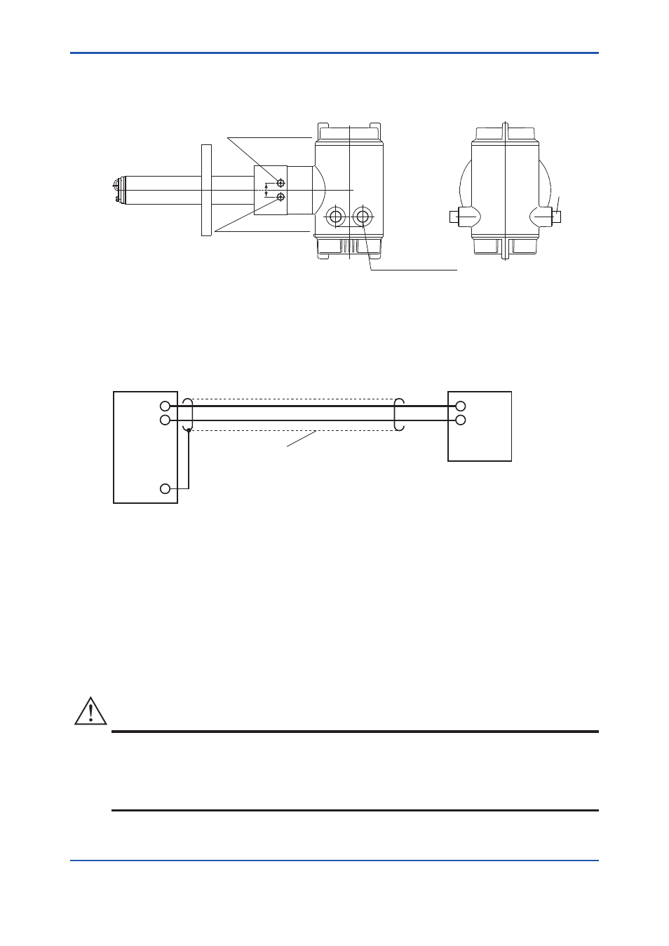
5.1.3 Mounting of Cable Gland
For each wiring inlet connection of the equipment, mount the conduit appropriate for the screw size or
a cable gland.
F5.3E.ai
25
4-G1/2,2-1/2NPT etc.
Cable connection port
Cable gland
Rc1/4 or 1/4NPT
Reference gas inlet
Rc1/4 or 1/4NPT
Calibration gas inlet
Figure 5.3
Cable Gland Mounting
5.2 Wiring for Analog Output
This wiring is for transmitting 4 to 20mA DC output signals to a device, e.g. recorder. Maintain the load
resistance including the wiring resistance of 550Ω or less.
+
-
AO(+)
AO(
-
)
FG
F5.4E.ai
Shielded cables
Analyzer
Receiver
Figure 5.4
Wiring for Analog Output
5.2.1 Cable Specifications
Use a 2-core shielded cable for wiring.
5.2.2 Wiring Procedure
(1) M4 screws are used for the terminals. Use crimp-on terminals appropriate for M4 terminal
screws for cable connections. Ensure that the cable shield is connected to the FG terminal of the
equipment.
(2) Be sure to connect (+) and (-) polarities correctly.
CAUTION
• Before opening the cover, loosen the lock screw. If the screw is not loosened first, the cover
will be improperly engaged to the body, and the terminal box will require replacement. When
opening and closing the cover, remove any sand particles or dust to avoid gouging the thread.
• After screwing the cover on the equipment body, secure it with the lock screw.