Wiring diagram - b, Wiring diagrams, Guardian control™ solutions – Lincoln Electric P709 GUARDIAN CONTROL SOLUTIONS User Manual
Page 74
F-2
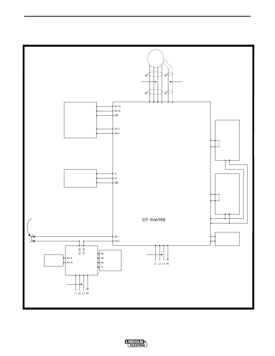
WIRING DIAGRAMS
F-2
GUARDIAN CONTROL™ SOLUTIONS
X3-1 PIN to C PIN (TROUBLE ALARM)
SEE LEADS ON
WIRING DIAGRAM-A
WIRING DIAGRAM - B
X3-20 PIN to NC PIN (TROUBLE ALARM)
X3-10
X3-9
Solenoid valve 3
Mains
380-480V 50/60Hz
CB-MDB/PMD
X3-8
X3-7
Sliding valve 2
X3-6
X3-5
S6
Sliding valve 1
Reed contact 2
S5
Reed contact 1
X3-12
X3-11
Solenoid valve 2
Solenoid valve 1
M
Refer to fan size
for wire diameter
( 2 x 18 AWG ) or ( 2 x 0.75 mm² )
PTC motor protection cable
3 Ø ∆
Alarm sequence:
1) Fire alarm sounder, shut down motor, close sliding valves, close solenoid valve.
2) Delay 5 seconds: release extinguishing agent (FlameShield) for 60 seconds.
All wiring not specified: 5 x 0.5 mm²
PE U V W
Variable frequency drive
Danfoss
13
33
LIMIT SWITCH 2
LIMIT SWITCH 1
BARRIER VALVES
COMPRESSED AIR VALVE
FIRE ALARM
FILTER PRESSURE
MONITOR
COMPRESSED AIR SWITCH
1
2
GND
PT-1000/2500
PRESSURE MONITOR
OILSHIELD
Mains
380-480V 50/60Hz
Refer to connected
load for wire diameter.
PRESSURE
SWITCH 2
LIGHT TOWER
X3-43
X3-42
X3-41
X3-40
Refer to connected
load for wire diameter
- Invertec V310-T DC (2 pages)
- VANTAGE 500 (CE) 11575 (50 pages)
- INVERTEC V350-PRO SVM152-A (155 pages)
- IMVERTEC V160-T (36 pages)
- IDEALARC CV-300 (112 pages)
- INVERTEC POWER WAVE 450 SVM112-B (293 pages)
- AUTO-DARKENING HELMET IM10001 (12 pages)
- IM10111 IDEALARC R3R-500-I (28 pages)
- IM10110 IDEALARC R3R-400 (25 pages)
- IM10051 INVERTEC V311-T AC_DC (38 pages)
- IM10059 SQUARE WAVE TIG 175 (30 pages)
- IM10096 POWER MIG 256 (37 pages)
- IM10096 POWER MIG 256 (38 pages)
- IM10105 POWER MIG 350MP (47 pages)
- IM10115 FLEXTEC 650 (42 pages)
- IM10132 FLEXTEC 650 (36 pages)
- IM10132 FLEXTEC 650 (56 pages)
- IM10018 IDEALARC DC-600 VRD (55 pages)
- IM10107 IDEALARC DC-400 (40 pages)
- IM10062 FLEXTEC 450 (72 pages)
- IM10091 FLEXTEC 450 CE (40 pages)
- IM10094 RED-D-ARC FX450 (31 pages)
- IM10157 12_24V 10A Auto HF Household Charger (16 pages)
- IM10139 JUMP STARTER (12 pages)
- IM10149 POWER WAVE ADVANCED MODULE (46 pages)
- IM10102 AIR VANTAGE 650 (60 pages)
- IM10103 AIR VANTAGE 700 (AU) (57 pages)
- IM10065 AIR VANTAGE 500 CUMMINS (54 pages)
- IM10066 AIR VANTAGE 500 (AU) (56 pages)
- IM10041 VANTAGE 500 CUMMINS (56 pages)
- IM10128 AIR VANTAGE 500 KUBOTA (AU) (56 pages)
- IM10090 ARC TRACKER (48 pages)
- IM10147 AUTO-DARKENING HELMET (12 pages)
- IM10087 AutoDrive 19 CONTROLLER (28 pages)
- IM10125 AutoDrive 19 TANDEM (34 pages)
- IM10069 AutoDrive 4R100 (32 pages)
- IM10145 AUTOPRO 20 (24 pages)
- IM10025 BIG RED 500 (40 pages)
- IM10019 BIG RED 600 (41 pages)
- IM10005 BULLDOG 140 (46 pages)
- IM10074 BULLDOG 5500 (56 pages)
- IM10067 CENTURY AC120 (20 pages)
- IM10109 CIRCULATOR (33 pages)
- IM10109 CIRCULATOR (36 pages)
- IM10153 CLASSIC 300 HE (60 pages)