Installation, Heat detector set, A-32 – Lincoln Electric P709 GUARDIAN CONTROL SOLUTIONS User Manual
Page 39: Description, Components, Location, Electrical connection -zone 2
A-32
INSTALLATION
GUARDIAN CONTROL™ SOLUTIONS
A-32
HEAT DETECTOR SET
DESCRIPTION
The Heat Detector Set consists of two temperature
detectors that are installed in the filter housing. When
they detect a temperature of 190°F (88°C) or more,
they send a signal to the Guardian™ Panel to activate
the fire suppression system.
COMPONENTS:
• Heat Detector (2) With Junction Box (2)
• Cable Gland M25 (2)
• Nut Cable Gland M25 (2)
• Cable Gland M16 (4)
LOCATION
See Figure A.31.
• 1st heat sensor: on top of filter housing (A)
• 2nd heat sensor: in hopper just above dustbin (B)
• 1 heat detector set per filter module (number of hop-
pers = number of heat detector sets)
NOTE: It may be necessary to place sensors on the
front of filter housings when units are stacked.
See Figure A.32.
1. Drill the appropriate size hole in the sheet metal.
2. Mount the heat sensors in the filter housing(s) and
hopper(s); A = housing/hopper.
ELECTRICAL CONNECTION -ZONE 2-
To be sourced locally:
• Connection Wire: 5 x 20 AWG Shielded Cable
Wiring
One or more sets of temperature detectors must be
wired in parallel. The detectors act as one sensor and
are connected to Zone 2 (See Electrical Wiring
Diagram).
1. Connect the heat sensors using shielded cables.
See Wiring Diagram.
End of line resistor
The last detector that is wired to the fire detection
panel Guardian™ Panel must be fitted with an End Of
Line resistor according to Figure A.33. The End Of Line
resistor of the heat detector is supplied with the fire
detection panel and can be found in Zone 2 of the rel-
evant terminal.
1. Take the End Of Line resistor from Zone 2 of the
Guardian™ Panel and place it in the last heat detec-
tor. See Figure A.33.
The End Of Line resistor makes it possible for the fire
detection panel to monitor the system for an open cir-
cuit.
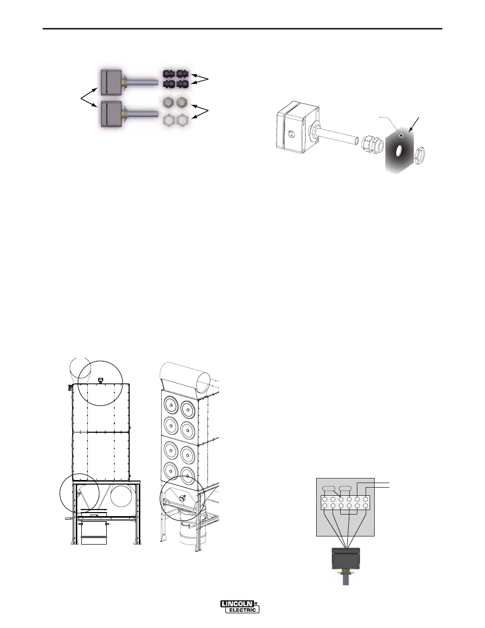
FIGURE A.30 – HEAT DETECTOR SET (2)
HEAT
DETECTORS
GLANDS
NUTS
FIGURE A.31 – HEAT SENSOR LOCATIONS
A
C
A
B
B
FIGURE A.32 – HOUSING / HOPPER
A
SHEET
METAL
FIGURE A.33 – HEAT SENSOR WITH
END OF LINE RESISTOR
RAL
REOL
black
2x black
2x white
white
from other detector
or panel