Installation, Warning, A-38 – Lincoln Electric P709 GUARDIAN CONTROL SOLUTIONS User Manual
Page 45: Post installation checks, Electrical connection -zone 3
A-38
INSTALLATION
GUARDIAN CONTROL™ SOLUTIONS
A-38
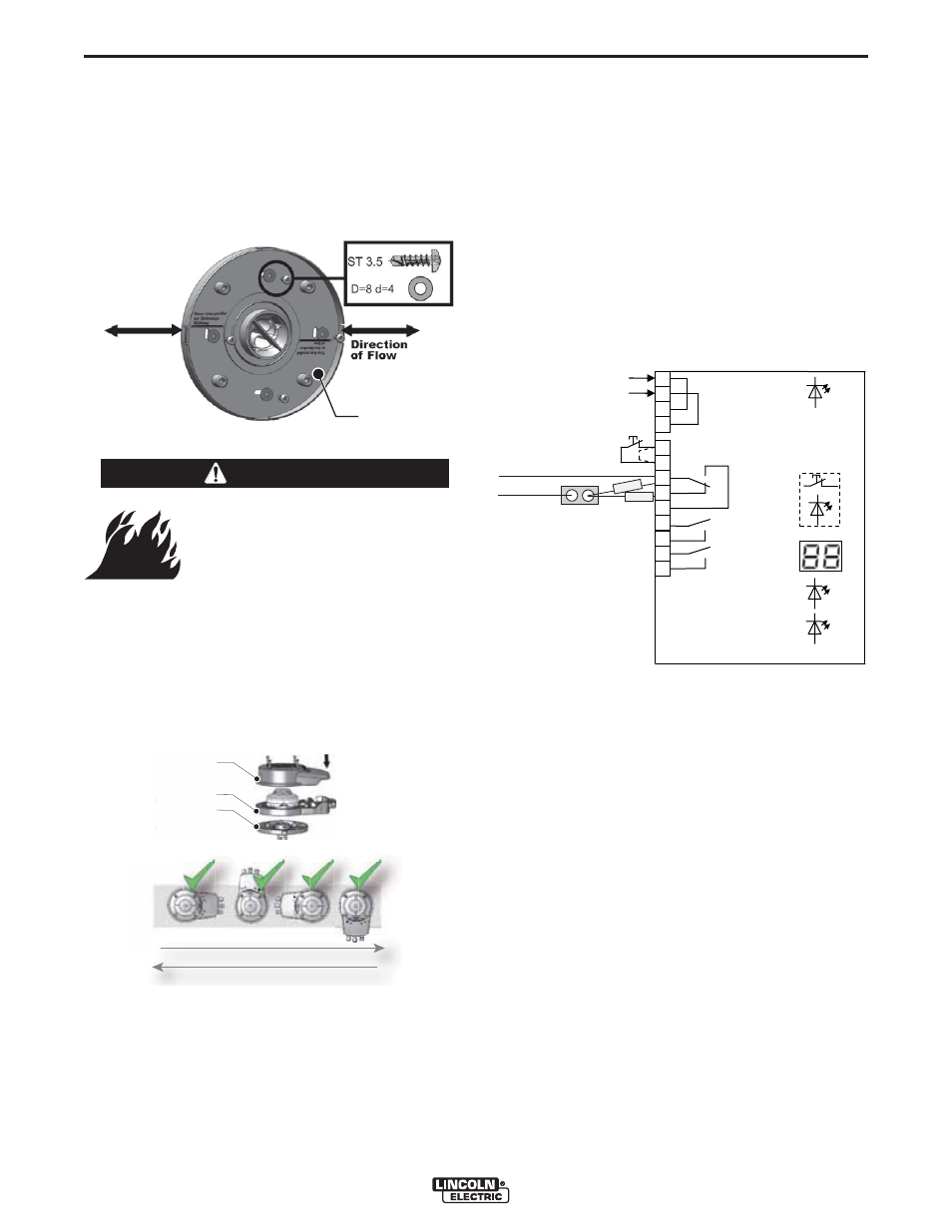
See Figure A.43.
10. Determine the airflow direction and turn the
adapter plate (A) so that the arrowed line on the
adapter plate is parallel to the airflow direction.
11. Fasten the adapter plate to the mounting bracket
using 4 self-tapping screws with washers.
See Figure A.44.
12. Mount the upper (B) and lower (A) part of the hous-
ing on the adapter plate (C). The housing can be
mounted in any position parallel to the airflow
direction (D).
POST INSTALLATION CHECKS
1. Check that all screws are secure.
2. Check that adapter plate is properly mounted in rela-
tion to the airflow direction.
ELECTRICAL CONNECTION -ZONE 3-
To be sourced locally:
• connection wire: 5 x 20 AWG shielded cable
Wiring
The NC (normally closed) terminals 11 and 12 are
used for connection to the Guardian™ Panel.
See Figure A.45.
1. Connect terminals 11 and 12 to Zone 3 of the
Guardian™ Panel.
NOTE: If the LED display showing the contamination
level is not visible from the floor, terminals 16
and 17 can be used to connect an external 24V
warning device.
End of line resistor
1. Take the End Of Line resistor from the terminal of
Zone 3 of the Guardian™ Panel.
2. Place the End Of Line resistor in the smoke detector
over connection 11 and 12 in accordance with
Figure A.45.
The End Of Line resistor is 5k1 ohm.
Alarm resistor
The smoke detector is fitted with an alarm resistor of
470 ohm placed in series with the switching contact cir-
cuit. The resistor is placed between terminal 12 of the
smoke detector and Zone 3 of the Guardian™ Panel.
This alarm resistor has no function and does not inter-
fere with the functionality of the Guardian™ Panel fire
detection panel. In case of a short circuit, the fire alarm
will activate.
FIGURE A.43
A
Airflow direction of air sampling tube
must be correct to ensure proper
functioning of the smoke detector.
-----------------------------------------------------------------------
WARNING
FIGURE A.44
A
B
C
D
FIGURE A.45
KRM-2, 24 V
Power supply
24 V AC/DC
Test/Reset
9
10
11
12
13
14
15
green
16
17
yellow
blue
Smoke alarm
Smoke alar
m
Serv
ice signal
Contamination
red
Test/Reset
3
4
Power supply
230 V AC
1
2
KRM-2
REOL
RAL
ShieldControl
Zone 3+
ShieldControl
Zone 3–