Installation, A-18, Inspection hatches (recommended option) – Lincoln Electric P709 GUARDIAN CONTROL SOLUTIONS User Manual
Page 25: Manual damper (option)
A-18
INSTALLATION
GUARDIAN CONTROL™ SOLUTIONS
A-18
NOTE: Although it is possible to mount the dustbin
directly to the Spark Guardian™, the installa-
tion of a vertical duct of at least 3 feet between
Spark Guardian™ and dustbin enhances fire
safety. The larger the distance to the dustbin,
the safer. Do not mount the dustbin in a “hang-
ing” position. A structure that is capable of
supporting a full dustbin (100 lbs.) is necessary
and shall be in place at all times under the
dustbin.
NOTE: For weight reasons it is recommended to place
the dustbin on a small pallet to facilitate
removal.
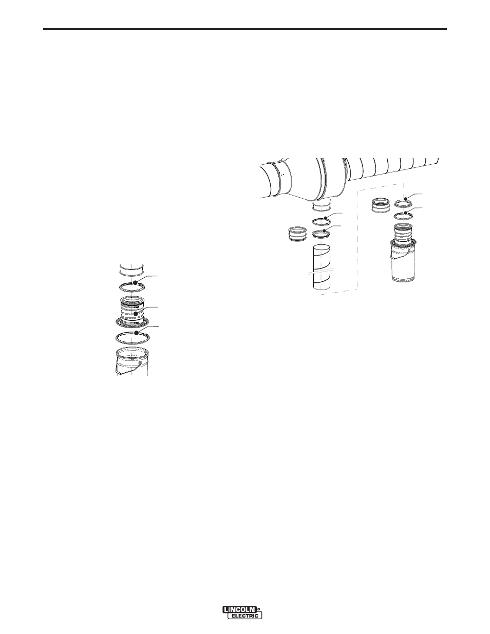
To mount the dustbin, proceed as follows.
1. Observe the mounting orientations indicated in
Figure A.6.
See Figure A.9.
2. Place the dustbin cover (B) on the dustbin of your
choice and connect it using the quick connect cou-
pling (C).
Direct mounting to Spark Guardian™:
1. Place the dustbin underneath the Spark Guardian™.
2. Connect it to the Spark Guardian™ using the duct
clamp (A).
3. Tighten the clamp using a wrench.
In this case the following parts become unnecessary:
• Connection ring (2) Ø 8 in. (200 mm)
• Duct clamp Ø 7.87 in. (200 mm)
Mounting via vertical duct Ø 200 mm/8 inch: (See
Figure A.10.)
• Duct metric size (mm):
Place a connection ring Ø 200 mm (B) at either side
of the duct and fasten them using self-tapping screws
(min. 4).
• Duct imperial size (inch):
Place a reducer metric-imperial Ø 8 in. (B) at either
side of the duct and fasten them using self-tapping
screws (min. 4).
1. Connect the duct to the Spark Guardian™ using a
duct clamp (A). Tighten the clamp using a box
wrench.
2. Place the dustbin underneath the duct.
3. Connect it to the duct using the duct clamp (C).
Tighten the clamp using a box wrench.
INSPECTION HATCHES (RECOMMENDED
OPTION)
See Figure A.7 for recommended position of the
inspection hatches.
1. Make cut outs in the horizontal and/or vertical duct
using the template supplied with the inspection
hatches.
2. Insert the hatches in the cut outs.
3. Turn the handles 90° to fasten them and make the
ducts airtight.
NOTE: Refer to the mounting instruction supplied with
the inspection hatches.
MANUAL DAMPER (OPTION)
The manual damper can be installed in any appropri-
ate position in the vertical duct.
The function of the manual damper is to allow for the
dumping of the dustbin without shutting off the system.
1. Install the manual damper in accordance with the
instruction sheet supplied with the damper.
2. Open the damper by turning the handle in vertical
position.
FIGURE A.9 – DUSTBIN MOUNTING
B
A
C
FIGURE A.10 – DUSTBIN MOUNTING
VIA VERTICAL DUCT
A
B
B
C
inch
mm
mm
inch