Operation, Component description and operation – Lincoln Electric P709 GUARDIAN CONTROL SOLUTIONS User Manual
Page 55
B-5
OPERATION
GUARDIAN CONTROL™ SOLUTIONS
B-5
7. Reset the panel, detectors and system control
panel and make sure no fault indicators are lit. If
any fault indicator is lit, the appropriate input or out-
put must be checked and cleared before proceed-
ing. Make sure all detectors are reset. See Wiring
Diagram.
8. After satisfactory testing, make all final connections
to the sequential activator(s) and Flame
Guardian™ generator(s). See Wiring Diagram.
9. Make sure panel is in RUN mode. When connec-
tions are correct, all indicators are off and the dis-
play shows the text System “OK”.
COMPONENT DESCRIPTION AND
OPERATION
GUARDIAN™ PANEL
Guardian™ Panel is a fire detection panel (UL
Standard 862) with a separate manual call point. It has
three detection zones all of which are capable of acti-
vating the Flame Guardian™ fire extinguishing
aerosols.
The panel makes it possible to connect additional man-
ual call points.
The Guardian™ Panel has two back-up batteries to
allow for continuous operation in the event of a tempo-
rary power failure.
HEAT DETECTOR SET
The Heat Detector Set consists of two temperature
detectors that are installed in the filter housing. When
they detect a temperature of 190°F (88°C) or more,
they send a signal to the Guardian™ Panel to activate
the fire suppression system.
SPARK DETECTOR SET
There is a set of two infrared spark detectors. The
spark detectors are sensitive to the IR light between
0.4 to 1.1 microns wavelength.
When glowing particulate from the burning filter enters
the field of view on the detector, the detector responds
by sending a signal to the Guardian™ Panel fire detec-
tion panel. The Guardian™ Panel activates the fire
suppression system.
SMOKE DETECTOR
The Smoke Detectorʼs operation is based on light scat-
tering by the air sampling tube. The sampling tube
transports the air to the smoke detector. When smoke
is detected, it sends a signal to the Guardian™ Panel.
The Guardian™ Panel activates the fire suppression
system. The smoke detector is fitted with the following
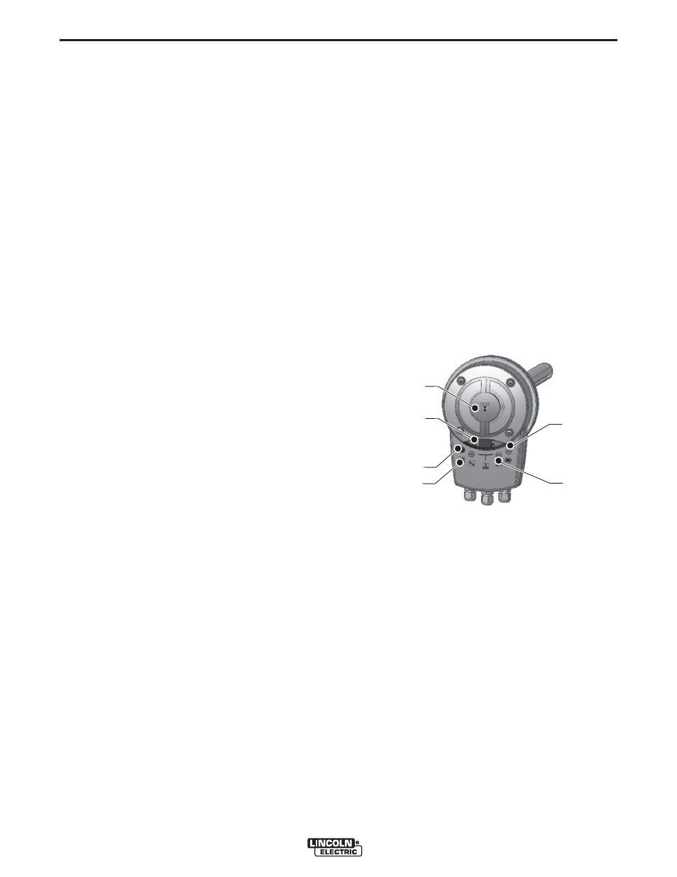
LEDs, indicators and features:
See Figure B.3.
A. Opening for test spray
B. LED display: indicates the contamination status of
the sensor and need for maintenance
C. Red LED: alarm; also reset button and functional
check
D. Yellow LED: failure
E. Blue LED: lack of airflow (<1 m/s)
F. Green LED: Operation Normal
SLIDING VALVES
When the filter system is in operation, the sliding
valves are open. In the event of an alarm signal, power
failure or when the fan is switched off, the valves are
closed. Correct closing of the valves is monitored by a
reed switch contact.
In case of fire, the sliding valves close automatically.
This cuts off air flow to the fire. This will also minimize
risk of escalation and spreading of smoke.
FIGURE B.3 – FEATURES
A
B
C
D
E
F