Installation, Solenoid valve – Lincoln Electric P709 GUARDIAN CONTROL SOLUTIONS User Manual
Page 29
A-22
INSTALLATION
GUARDIAN CONTROL™ SOLUTIONS
A-22
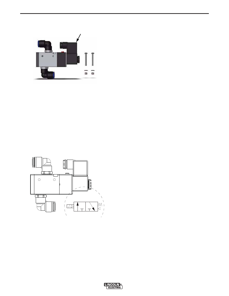
SOLENOID VALVE
DESCRIPTION
See Figure A.18.
Normally closed 3-way 2-position solenoid valve.
When the connected filter system is in operation, the
solenoid is activated and compressed air is supplied to
the cleaning system of the filter (port P and A are
open). If there is a fire alarm or power failure, the sole-
noid will return to its normally closed (NC) position,
closing port P and opening port R. In this position the
compressed air escapes from the pressure tanks. It
also prevents fresh oxygen from reaching the filter.
COMPONENTS
• 3/2 solenoid valve, including electrical entry terminal
and 2 swivel elbow adapters
• Screw M4x35 (2)
• Washer M4 (2)
• Locknut M4 (2)
LOCATION
The solenoid valve is placed in the main compressed
air line between pressure reducer and filter unit. It is
recommended to mount the valve on the filter housing.
• Mount the solenoid valve at an accessible location.
• Refer to the Pneumatic Diagram for more details
ELECTRICAL CONNECTION
To be sourced locally:
• Connection wire: 5 x 20 AWG
Wiring
1. Connect the solenoid valve to the system control
panel in accordance with the Electrical Wiring
Diagram.
Compressed air connection
The solenoid valve is fitted with a 12 mm compressed
air tube connection.
1. Connect the solenoid valve to compressed air.
2. Check compressed air connections of filter system.
FIGURE A.17
SOLENOID
VALVE
FIGURE A.18 – SOLENOID VALVE
A
P
R
A
P R