Installation – Lincoln Electric P709 GUARDIAN CONTROL SOLUTIONS User Manual
Page 38
A-31
INSTALLATION
GUARDIAN CONTROL™ SOLUTIONS
A-31
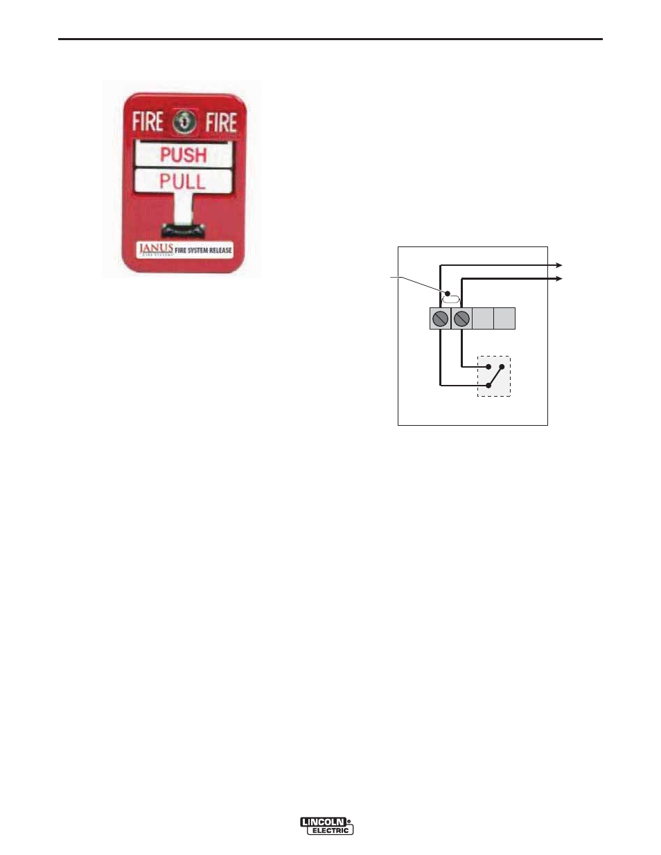
MANUAL CALL POINT
DESCRIPTION
Manual pull station is a switch used to activate the fire
alarm and fire suppression system.
To operate push in the bar marked “PUSH” and pull the
handle marked “PULL” on the front of the unit as far
down as it will go. At that point, the handle will lock in
place and will be easily visible up to 50 feet away.
COMPONENTS:
• Manual Call Point
• Key
LOCATION
• Where it will be easy for the operator to reach it
• Indoors
NOTE: Do not mount the manual call point to the filter
system. It may not be accessible if there is a
fire.
ELECTRICAL CONNECTION
To be sourced locally:
• Connection Wire: 5 x 20 AWG Shielded Cable
See Figure A.29.
1. Connect the manual call point to Zone 4 of the
Guardian™ Panel in accordance with the Electrical
Wiring Diagram.
2. Take the End Of Line resistor 5k ohm mounted in
the terminal strip of Zone 4 and place it in the termi-
nal strip of the manual call point (A).
RESET
1. Using the proper key, open the cover.
2. Move the toggle switch into the “on” or “run” position.
3. Place the “push” and “pull” handles back into thier
ready positions. See Figure A.29.
4. Close and lock cover.
FIGURE A.28 – MANUAL CALL POINT
FIGURE A.29 – ELECTRICAL CONNECTION
NC
NO
field wiring
toggle
switch
white
red
terminal strip
REOL
A