Installation, Warning, A-35 – Lincoln Electric P709 GUARDIAN CONTROL SOLUTIONS User Manual
Page 42: Electrical connection -zone 1, Guardian control™ solutions, Figure a.38, Figure a.39
To prevent a malfunction of the
spark detector, ensure that the green
earth/ground wire is properly con-
nected.
-----------------------------------------------------------------------
WARNING
Failure to remove the End Of Line
resistor over Zone 1 will disable the
monitoring function.
-----------------------------------------------------------------------
WARNING
A-35
INSTALLATION
GUARDIAN CONTROL™ SOLUTIONS
A-35
See Figure A.38.
7. Insert the spark detector lens (A) into the flange (C).
8. Fasten the detector using the supplied mounting
screw (B).
9. Follow the same procedure for the second spark
detector.
NOTE: To prevent false alarms, ensure that no light
can get between the flange and the duct. Seal
any holes with metal foil. Do not use duct tape
since this may let through infrared light.
ELECTRICAL CONNECTION -ZONE 1-
To be sourced locally:
• Connection wire: 5 x 20 AWG shielded cable
Wiring
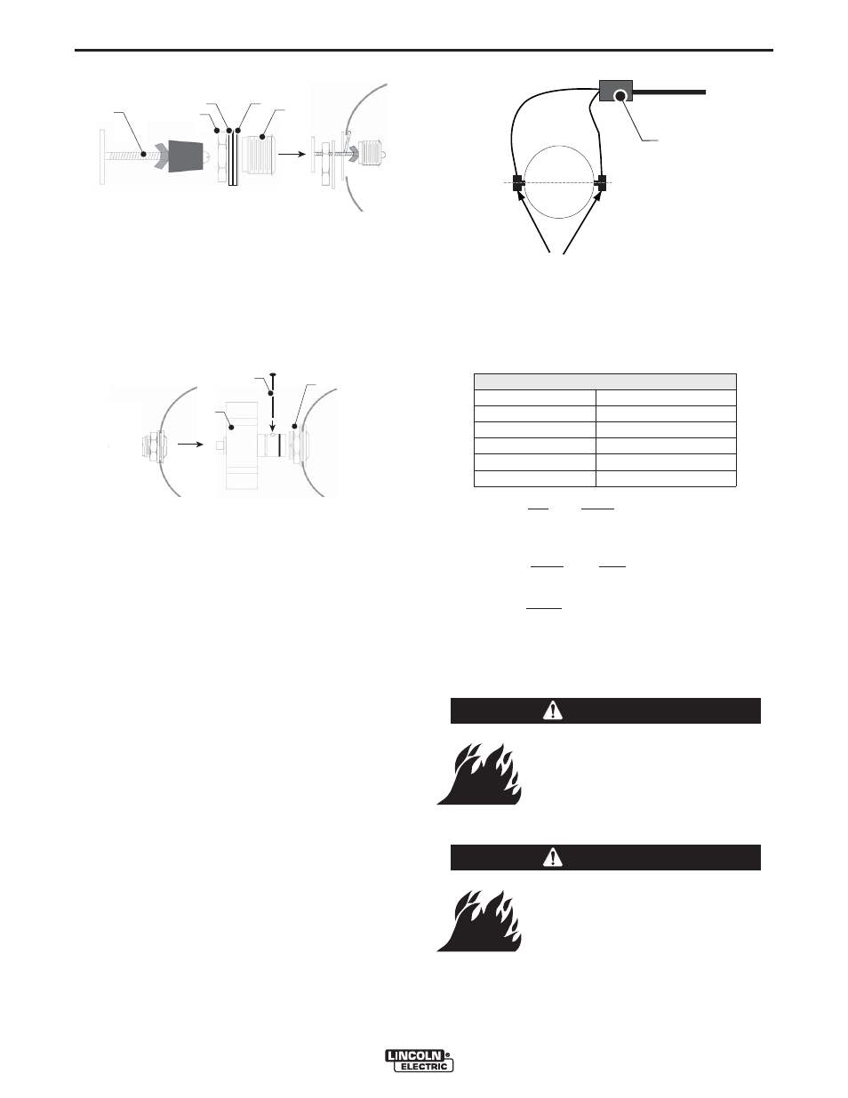
See Figure A.39.
The spark detectors (A) must be wired in parallel in the
supplied junction box (B). Each set consists of one
spark detector with End Of Line resistor (“End Of Line”)
and one without (“no End Of Line”), which is marked on
the spark detector housing.
• Mount the spark detector “End Of Line” in parallel
after the one without (“no End Of Line”) according to
the Electrical Diagram.
The spark detectors are provided with the following
colored wires:
• Connect the red and black wire to the 24V auxiliary
connection of the Guardian™ Panel fire detection
panel.
• Connect the white and blue wire to Zone 1 of the
Guardian™ Panel.
• Connect the green wire to earth/ground.
The End Of Line resistor over Zone 1 of the
Guardian™ Panel has become obsolete and has to
be removed because it is already pre-mounted in
the spark detector.
FIGURE A.37
A
B
C
D
E
FIGURE A.38
A
B
C
FIGURE A.39
A
(x2)
B
Color codes wiring
C
D
V
4
2
+
d
e
R
C
D
V
0
k
c
a
l
B
+
E
N
O
Z
r
o
L
A
N
G
I
S
V
4
2
e
t
i
h
W
–
E
N
O
Z
e
u
l
B
T
S
E
T
n
w
o
r
B
d
n
u
o
r
g
/
h
t
r
a
e
n
e
e
r
G