Installation, Warning, A-20 – Lincoln Electric P709 GUARDIAN CONTROL SOLUTIONS User Manual
Page 27: Electrical connection, Compressed air connection
A-20
INSTALLATION
GUARDIAN CONTROL™ SOLUTIONS
A-20
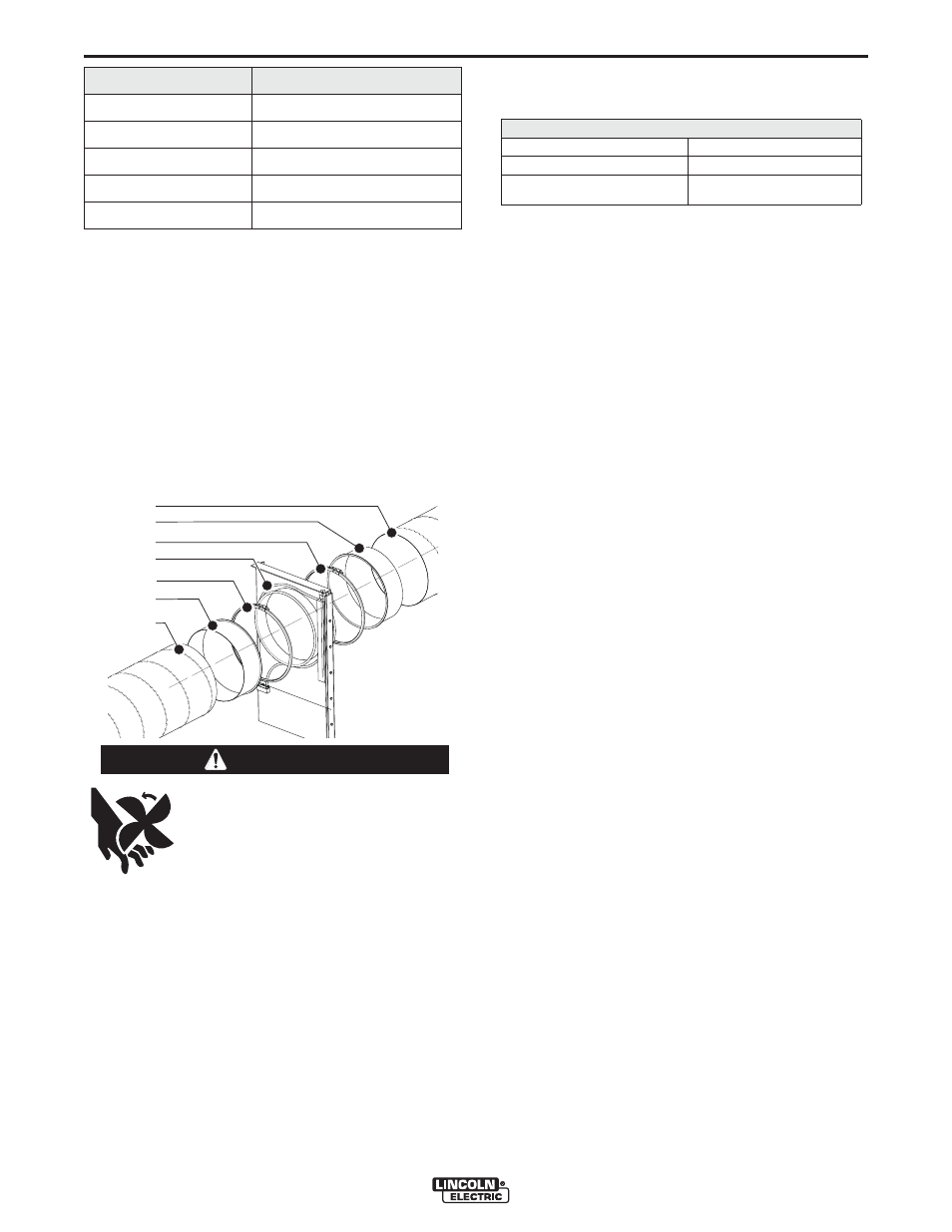
4. Slide a connection flange (B) into both duct ends
(A).
5. Place the sliding valve (D in between and fasten it
using the quick connect couplings (C).
6. Fasten the connection flanges using self-tapping
screws.
NOTE: The valves must be mounted straight and
without tension on the shell/housing to guar-
antee airtightness and to avoid noise from air-
flow.
ELECTRICAL CONNECTION
To be sourced locally:
• Connection wire: 5 x 20 AWG cable
Wiring
1. Connect the sliding valves to the system control
panel in accordance with the Electrical Wiring
Diagram.
2. Connect the reed contacts to the system control
panel in accordance with the Electrical Wiring
Diagram.
COMPRESSED AIR CONNECTION
1. Connect the sliding valves to compressed air source
per the Pneumatic Diagram.
Setting closing speed of the sliding valves
The closing speed of the valves is set by the air pres-
sure.
1. Set the closing speed of the valves to 4-5 seconds
by adjusting the air pressure to 5 BAR.
Do not set the valves to faster than 4 seconds. If there
is a fire alarm, the fan is switched off and the sliding
valves are closed. The 4 seconds gives the fan enough
time to reduce speed and prevents damage to the duct
by negative pressure. Do not select speeds slower
than 5 seconds, since the Flame Guardian™ modules
are activated 5 seconds after the fire alarm.
Post installation checks
• Check electrical connections.
• Check pneumatic connections.
• Check that nuts and bolts are secure.
Moving parts can cause injury.
If valve is mounted in an accessible
area, provide shroud and warning
label to prevent access.
-----------------------------------------------------------------------
WARNING
FIGURE A.14
B
A
B
A
C
D
C
Compressed air specifications
Compressed air connection
Recommended operational pressure
4-5 bar (max. 9 bar)
o
t
g
n
i
d
r
o
c
c
a
e
e
r
f
-
l
i
o
d
n
a
y
r
d
y
t
i
l
a
u
Q
ISO 8573-3 class 6
6 mm
Type of sliding valve
Duct length to be removed
.
n
i
4
.
0
-
/
+
.
n
i
6
.
1
1
0
1
-
V
S
.
n
i
4
.
0
-
/
+
.
n
i
6
.
1
1
2
1
-
V
S
.
n
i
4
.
0
-
/
+
.
n
i
6
.
1
1
6
1
-
V
S
.
n
i
4
.
0
-
/
+
.
n
i
0
.
5
1
0
2
-
V
S
.
n
i
4
.
0
-
/
+
.
n
i
0
.
5
1
4
2
-
V
S
FIGURE A.15