Installation, Commissioning checklist – Lincoln Electric P709 GUARDIAN CONTROL SOLUTIONS User Manual
Page 48
A-41
INSTALLATION
GUARDIAN CONTROL™ SOLUTIONS
A-41
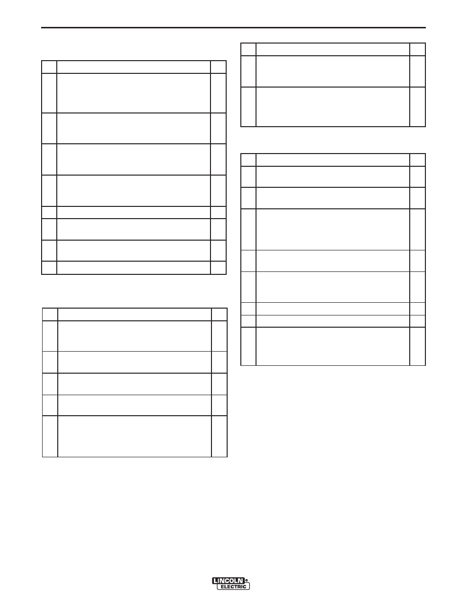
COMMISSIONING CHECKLIST
Guardian™ Panel
Heat Detector Set(s)
System Control Panel
Spark Detector Set
#
Check
OK
1. Is the system control panel correctly con-
nected to the Guardian™ Panel and other
peripheral equipment?
2. Is the system control panel functionally test-
ed on a test alarm and performing expected
actions (fan stop, sliding valves close, 3/2
solenoid opens)?
#
Check
OK
1. Is the Guardian™ Panel connected to a
clean electrical circuit or a circuit not subject
to regular power failures by other equip-
ment?
2. Is the panel placed in an environment with-
out excessive dust in line with IP 30 or other-
wise placed in a cabinet?
3. Are all cables checked for correct connection
in accordance with the Electrical Wiring
Diagram?
4. Are the End Of Line resistors removed from
the terminals that are in use and placed in
the connected equipment?
5. Are the cables well guided and secure?
6. Is a shielded cable being used for all detec-
tors as well as the manual call point?
7. Is the Guardian™ Panel switched to
RUN
mode?
8. No fault signals on the Guardian™ Panels?
#
Check
OK
1. Are the heat detectors placed on top inside
the filter housing and in the hopper just
above the dustbin?
2. Number of heat detector sets = number of
hoppers?
3. Are the heat detectors wired in parallel and
connected to Zone 2 of Guardian™ Panel?
4. Is an End Of Line resistor of 5k1 placed in
the last heat detector?
5. Is each heat detector being functionally test-
ed by gently heating it with a heat gun or
heat lamp and alarm signal being monitored
by Guardian™ Panel?
#
Check
OK
1. Are the spark detectors placed face to face in
the filter outlet duct?
2. Ensure that the spark detector is not mount-
ed on the bottom of the duct.
3. Are the spark detectors shielded against any
light and holes sealed with metal foil? Do not
use duct tape since this may let through
infrared light.
4. Are the spark detectors wired in parallel and
connected to Zone 1 of Guardian™ Panel?
5. Is the last spark detector in the circuit pro-
vided with End Of Line Resistor of 5k1 in
line with Guardian™ Panel?
6. Is the circuit properly grounded?
7. Are the lenses clean?
8. Are the spark detectors being functionally
tested through exposure to daylight and the
signal being monitored by Guardian™
Panel?