Installation, Flame guardian – Lincoln Electric P709 GUARDIAN CONTROL SOLUTIONS User Manual
Page 31
A-24
INSTALLATION
GUARDIAN CONTROL™ SOLUTIONS
A-24
FLAME GUARDIAN™
DESCRIPTION
The Flame Guardian™ is a fire suppression generator
designed to be installed directly into the filter system.
The Flame Guardian™ is activated by the Guardian™
Panel fire detection panel 5 seconds after a fire alarm
is activated.
The Flame Guardian™ is designed to suppress or
extinguish filter fires of EN 2 Class A and NFPA 10
Class A (normal or solid combustible material in the fil-
ters).
In 5 to 10 seconds, after a fire is detected, the filter is
filled with a potassium aerosol. This material reacts
with the free radicals in the flame. The free radicals
react with the aerosol instead of the fuel and the chain
reaction of fire is suppressed. The residue is a negligi-
ble amount of harmless and stable potassium hydrox-
ide salt (KOH).
After release of the aerosol, it remains active for at
least 30 minutes, this prevents the fire from reigniting.
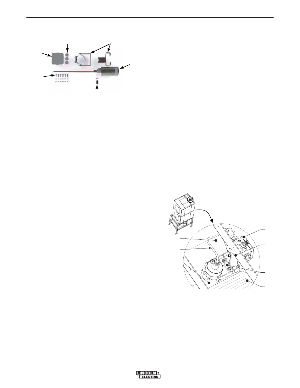
COMPONENTS:
1. Flame Guardian™ (200 or 500 g)
2. Mounting bracket (two piece)
3. Junction box
4. Metal cable gland/clamp
5. Plastic cable gland/clamp (2)
6. Mounting material
TRANSPORT AND STORAGE
To avoid damage, the following conditions for transport
and storage should be adhered to.
- Do not drop.
- Store between -58 and +212°F (-50 and +100°C).
- Relative humidity during transport and storage: max.
98%.
If Flame Guardian™ is stored in accordance with the
above mentioned conditions, shelf life of the aerosol
generator is 10 years.
INSTALLATION
• See Figure A.22 for the required number, type and
position of Flame Guardian™ generator in Statiflex
filter bank filter system.
NOTE: Failure to use the correct number, type and
position of the Flame Guardian™ generators
could compromise the effective fire response.
See Figure A.22 for number, type and position
of Flame Guardian™ generators.
COMPONENT LOCATIONS
See Figure A.21 and Figure A.22.
A. Filter cartridge
B. Junction box
C. Framework Statiflex filter bank (SFB)
D. Flame Guardian™ Frame
E. Flame Guardian™ (200 or 500)
F. Drilling Template (Not shown)
To install Flame Guardian™, proceed as follows.
See Figure A.23.
1. Connect one end of the High Temperature Lead to
the Flame Guardian™ Container. Leads are not
polarity sensitive.
2. Place the Connection Terminal inside the end of the
Flame Guardian™ Container and route the High
Temperature lead through the metal Strain Relief
Assembly, tighten. See Figure A.23. See Wiring
Diagram.
FIGURE A.20
1.
2.
4.
5.
3.
6.
FIGURE A.21
MDB
C
A
B
A
D
E
HIGH
TEMPERATURE
LEAD