Installation, Spark detector set – Lincoln Electric P709 GUARDIAN CONTROL SOLUTIONS User Manual
Page 41
A-34
INSTALLATION
GUARDIAN CONTROL™ SOLUTIONS
A-34
SPARK DETECTOR SET
DESCRIPTION
There is a set of two infrared spark detectors. The
spark detectors are sensitive to the near IR light
between 0.4 to 1.1 microns wavelength.
When glowing particulate from the burning filter enters
the field of view on the detector, the detector responds
by sending a signal to the Guardian™ Panel fire detec-
tion panel. The Guardian™ Panel activates the fire
suppression system.
COMPONENTS:
• Spark detector with alarm resistor and mounting
screw
• Spark detector End Of Line Resistor with alarm resis-
tor and mounting screw
• Junction box
• Installation set (hole saw Ø 1.5 inches (38 mm) and
insertion tool)
LOCATION
• In filter outlet duct
• Face to face (180° apart from each other) in the same
horizontal plane (3 OʼClock - 9 OʼClock)
• Minimum 2.5 times duct diameter from bend or
branch Example: If duct is 12 inches in diameter the
spark detector placement must be at least 30” away
from a bend or branch.
NOTE: To avoid dirtying the lens, never mount the
spark detectors on the bottom of the duct.
Sensors shall be mounted @ 3 and 9 oʼclock.
NOTE: The spark detectors must be installed directly
across from each other to maintain line of sight.
The spark detectors can be mounted without having
access to the inside of the duct. In this case you will
need the supplied insertion tool.
NOTE: Installation is easier if the inside of the duct is
accessible.
In case of a new or disconnected duct allowing
access to the inside, proceed as follows.
See Figure A.36.
1. Make a hole Ø 1.5 in. (38 mm) in the duct using the
supplied hole saw.
2. Mount the flange (D) in the duct using the split wash-
er (C), washer (B) and nut (A).
3. Tighten washer and nut on the flange.
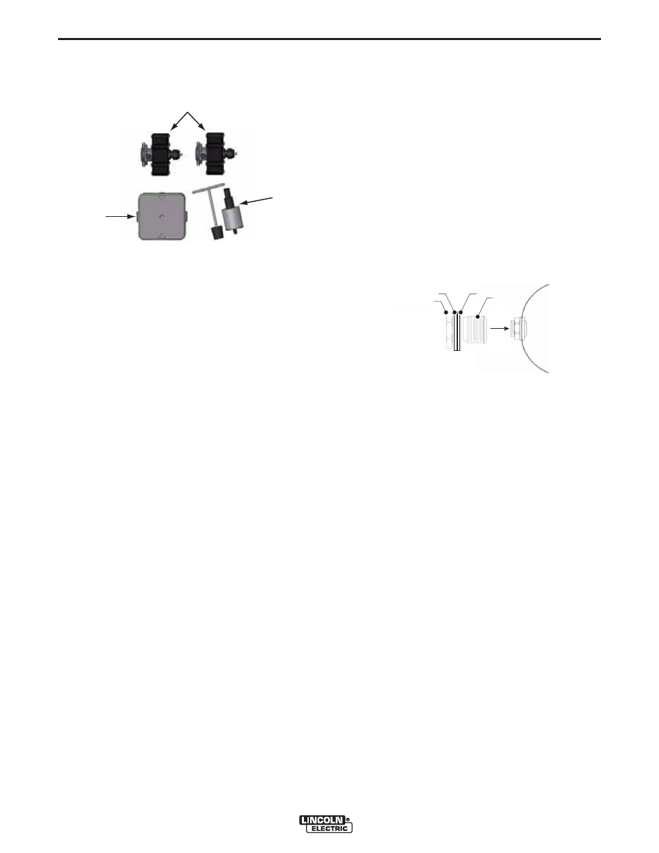
If there is no access to the inside of the duct, proceed
as follows.
See Figure A.37.
1. Make a hole Ø 1.5 in. (38 mm) in the duct using the
supplied hole saw.
2. Slip nut (B), washer (C) and split washer (D) on the
insertion tool (A) until the tool fits tightly on the
flange (E). The nut and washer should be loose on
the shaft of the tool.
3. Push the flange completely through the hole in the
duct and insert the split washer by rotating it into the
inside of the duct. Adding a gentle bend to the split
washer may be necessary.
4. Gently pull the flange back through the hole with the
insertion tool so it rests against the split washer
inside the duct.
5. Tighten washer and nut on the flange.
6. Remove the insertion tool by loosening the wing nut
and pulling straight back and twisting if required.
FIGURE A.35 – SPARK DETECTOR SET (2)
SPARK
DETECTOR(S)
JUNCTION
BOX
INSERTION
TOOL
FIGURE A.36
A
B
C
D