Installation – Lincoln Electric P709 GUARDIAN CONTROL SOLUTIONS User Manual
Page 49
A-42
INSTALLATION
GUARDIAN CONTROL™ SOLUTIONS
A-42
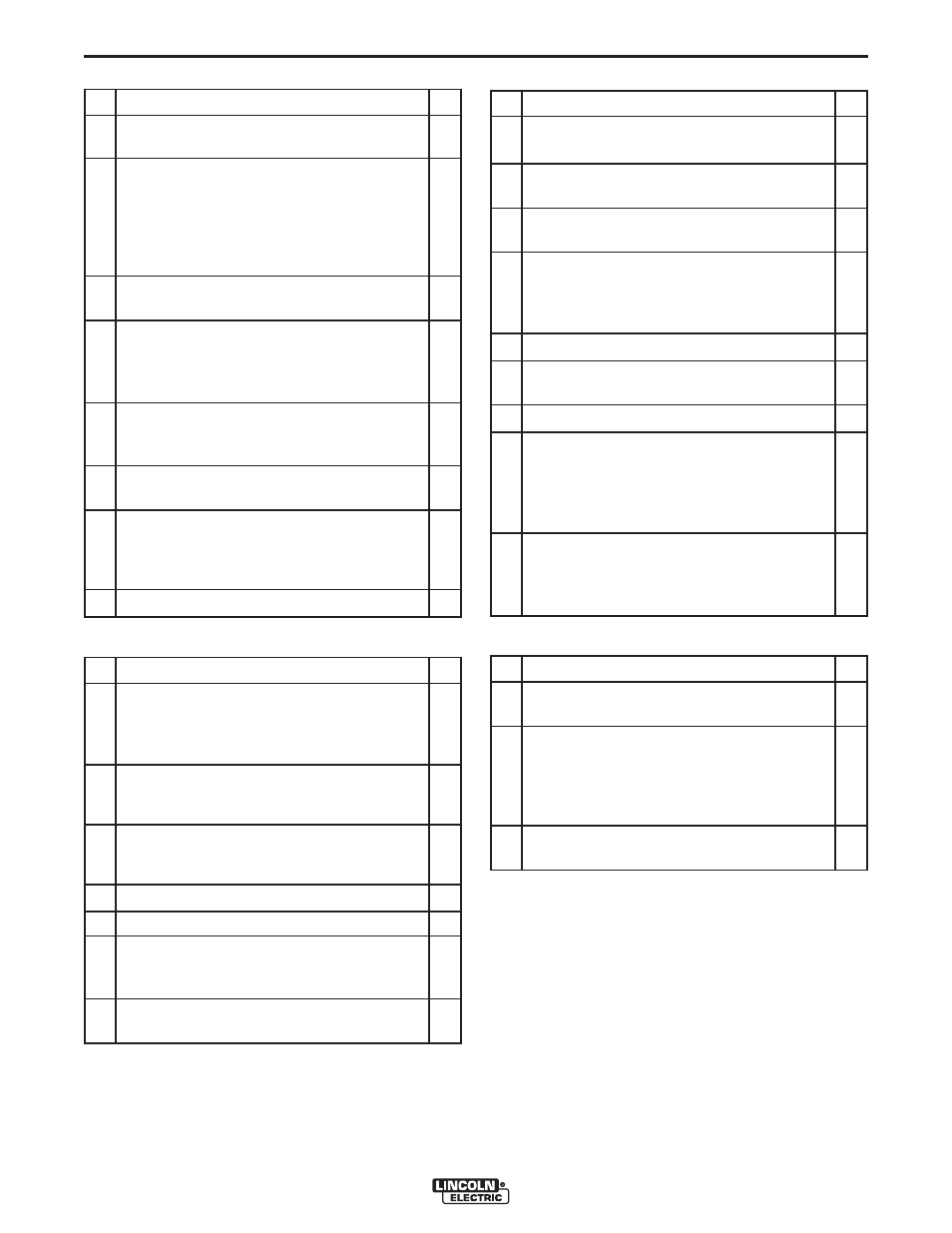
Smoke Detector
Manual Call Point and Fire Alarm Sounder
Flame Guardian™
Solenoid Valve
#
Check
OK
1. Is the smoke detector placed in the filter out-
let duct?
2. Is the LED display of the smoke sensor visi-
ble to read the contamination level? If not, an
external warning device, connected to the
detector circuit board terminal 16 and 17 is
recommended to monitor the sensor pollu-
tion.
3. Is the sampling tube correctly installed in
relation to the airflow?
4. Is the smoke detector sensor checked for
contamination level? In case of contamina-
tion level >69%, also indicated by a flashing
LED display, sensor must be replaced.
5. Is the End Of Line Resistor placed over ter-
minal 11 and 12 and in line with the
Guardian™ Panel?
6. Is the smoke detector connected to Zone 3 of
Guardian™ Panel?
7. Is the smoke detector being functionally test-
ed by test spray and alarm/reset button? Is
the signal being monitored by Guardian™
Panel?
8. Is the smoke detector being reset?
#
Check
OK
1. Are the manual call points marked or placed
close to the Guardian™ Panel in order to
avoid confusion with the general manual
alarm boxes of the building?
2. Is the End Of Line Resistor that was placed
in the manual call point in line with the
Guardian™ Panel?
3. Are the fire alarm sounders placed close to
the Guardian™ Panel and fitted with the cor-
rect End Of Line resistor 5k1?
4. Is the sounder set to your local tone?
5. Is sound level set to the maximum?
6. Is the manual call point being functionally
tested and monitored by the Guardian™
Panel?
7. Is the fire alarm sounder being tested and
activated by Guardian™ Panel?
#
Check
OK
1. Are Flame Guardian™ modules undam-
aged?
2. Is the correct number of Flame Guardian™
modules being installed?
3. Are the Flame Guardian™ modules placed in
the correct locations?
4. Are the Flame Guardian™ modules pushed
back to the middle stop of the mounting
bracket to secure a 10° downward release
angle?
5. Are all nuts and bolts secure?
6. Are the cables tension free, well guided and
secured by the cable glands/clamps?
7. Are the cable glands secure?
8. Has the internal wiring/electrical activation
been checked by measuring resistance over
the internal heating device of the Flame
Guardian™ with a current less than 5 mil-
liamps? The resistance must be 2 ohm.
9. Are, in combination with Guardian™ Panel,
the End Of Line resistor-diodes of 5k1 placed
in each junction box and the Flame
Guardian™ connected to output 2, 3 or 4?
#
Check
OK
1. Is the 3/2 solenoid valve mounted between
compressed air reducer (CAR kit) and filter?
2. Is the solenoid electrically and pneumatically
wired properly? When the solenoid is discon-
nected from power, the air from the com-
pressed air tanks of the filter system should
be released.
3. Is the solenoid functionally tested after a fire
test alarm in the complete system set up?