Installation, A-26, Electrical connection – Lincoln Electric P709 GUARDIAN CONTROL SOLUTIONS User Manual
Page 33: Post installation checks
A-26
INSTALLATION
GUARDIAN CONTROL™ SOLUTIONS
A-26
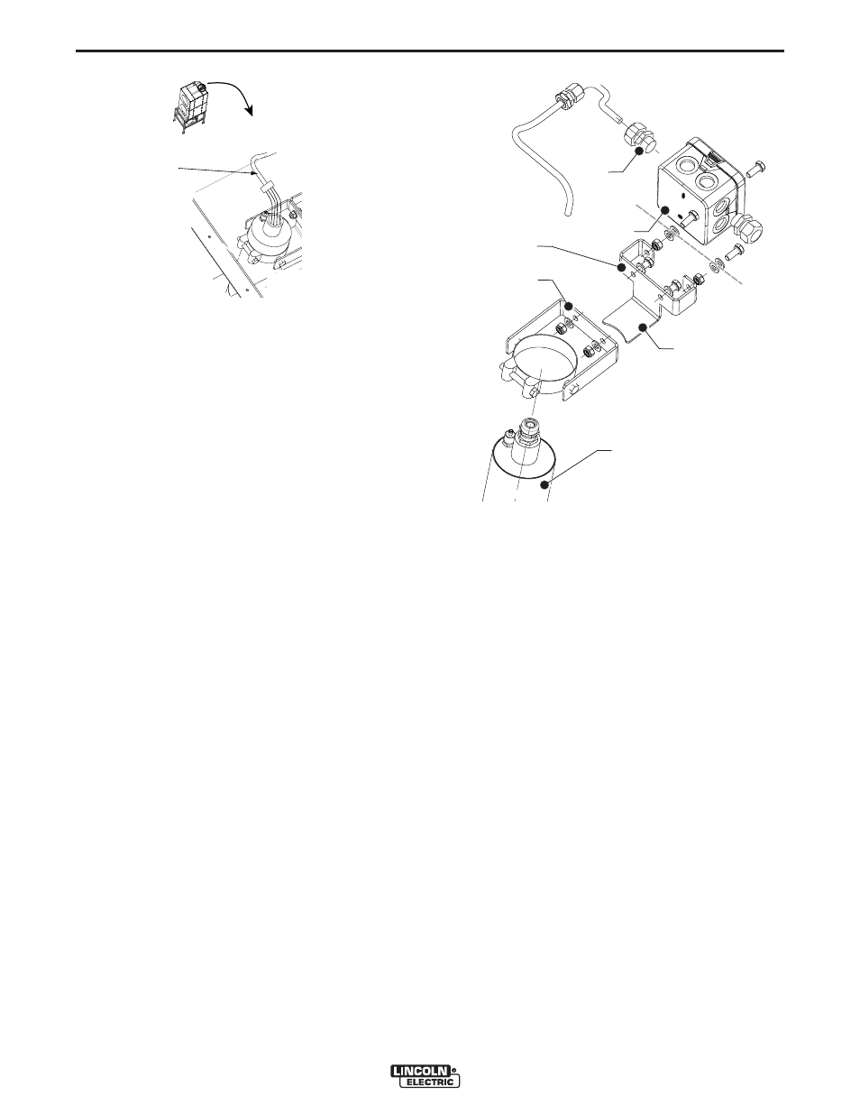
3. Loosely assemble mounting brackets. Hand tight-
en bolts, washers and locknuts. See Figure A.24.
4. Pre-drill two 5/16” holes exactly 3 3/16” apart on
front of filter housing. Use provided drilling tem-
plate.
5. Using #13 bolts, washers and locknuts, secure
mounting brackets to filter housing. See Figure
A.21.
6. Insert Flame Guardian™ Container into mounting
brackets previously installed. See Figure A.24.
7. Mount junction box to front of filter housing. Using
self tapping #10 x 3/4” screws. (not supplied).
NOTE: Mount with holes vertical. Pay attention
to components located behind mount-
ing holes.
8. Install plastic cable gland and high temperature
lead into workbox. See Figure A.24.
9. Connect low voltage shielded signal wire to the
leads from the flame guardian™ assembly.
10. Connect the low voltage shielded signal wire to
output #2 connection on the control unit. See
Wiring Diagram.
ELECTRICAL CONNECTION
To be sourced locally:
• Connection Wire: 5 x 20 AWG
Connection to Guardian™ Panel
• Place an End Of Line diode supplied with the
Guardian™ Panel in the junction box in series with
each Flame Guardian™, in accordance with the
Electrical Wiring Diagram.
POST INSTALLATION CHECKS
Before performing the functional test, check the follow-
ing mounting instructions.
• Wiring from and to the Guardian™ Panel.
• End Of Line resistor-diode in junction box.
• Correct position and flow angle (10°) of Flame
Guardian™.
• Secure all nuts and bolts.
FIGURE A.23
MDB
HIGH
TEMPERATURE
LEAD
FIGURE A.24
E
D
C
F
B
A
SFB