7 dvi display device connection, Figure 4-19: vga connector – IEI Integration KINO-HM551 User Manual
Page 77
KINO-HM551
Page 63
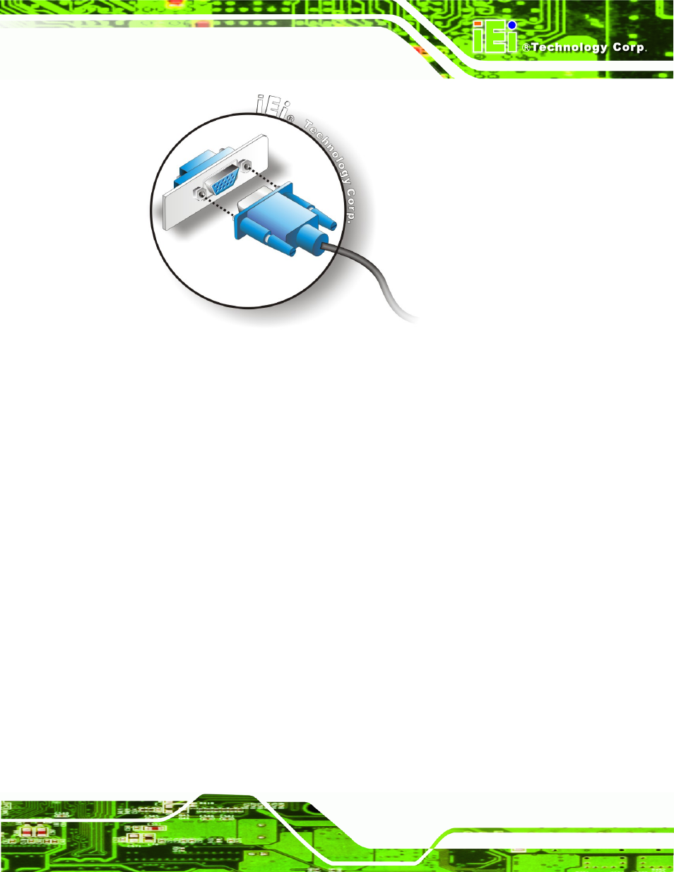
Figure 4-19: VGA Connector
Step 4:
Secure the connector. Secure the DB-15 VGA connector from the VGA
monitor to the external interface by tightening the two retention screws on either
side of the connector.
Step 0:
4.8.7 DVI Display Device Connection
The KINO-HM551 has a single female DVI-D connector on the external peripheral
interface panel. The DVI-D connector is connected to a digital display device. To connect
a digital display device to the KINO-HM551, please follow the instructions below.
Step 1:
Locate the DVI-D connector. The location of the DVI-D connector is shown in
another chapter.
Step 2:
Align the DVI-D connector. Align the male DVI-D connector on the digital
display device cable with the female DVI-D connector on the external peripheral
interface.
Step 3:
Insert the DVI-D connector
.
Once the connectors are properly aligned with the
male connector, insert the male connector from the digital display device into the
female connector on the KINO-HM551. See Figure 4-20.