5 jumper settings – IEI Integration PICOe-GM45A User Manual
Page 88
PICOe-GM45A Half-Size CPU Card
Page 88
Step 3:
Insert the DIMM. Once properly aligned, the DIMM can be inserted into the
socket. As the DIMM is inserted, the white handles on the side of the socket will
close automatically and secure the DIMM to the socket. See
787H
Figure 5-4.
Step 4:
Removing a DIMM. To remove a DIMM, push both handles outward. The
memory module is ejected by a mechanism in the socket.
Step 0:
5.5 Jumper Settings
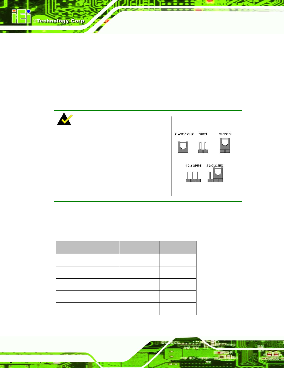
NOTE:
A jumper is a metal bridge used to close an
electrical circuit. It consists of two or three metal
pins and a small metal clip (often protected by a
plastic cover) that slides over the pins to connect
them. To CLOSE/SHORT a jumper means
connecting the pins of the jumper with the plastic
clip and to OPEN a jumper means removing the
plastic clip from a jumper.
Figure 5-5: Jumper Locations
Before the PICOe-GM45A is installed in the system, the jumpers must be set in
accordance with the desired configuration. The jumpers on the PICOe-GM45A are listed
in
829H788H
Table 5-1.
Description
Label
Type
AT Power Mode Setting
ATXCTL1
3-pin wafer
Clear CMOS
J_CMOS1
3-pin header
LVDS Panel Resolution
JP1
8-pin header
LVDS Voltage Select
J_VLVDS1
3-pin header
PCIe Status Select
JP2
2-pin header
Table 5-1: Jumpers