3 external interface panel connectors, 2 internal peripheral connectors, 1 atx power supply enable connector – IEI Integration PICOe-GM45A User Manual
Page 56
PICOe-GM45A Half-Size CPU Card
Page 56
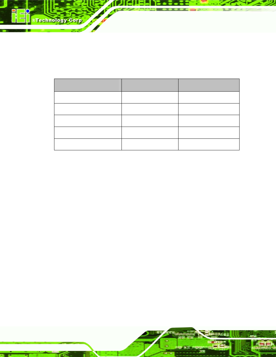
4.1.3 External Interface Panel Connectors
770H732H
Table 4-2 lists the rear panel connectors on the PICOe-GM45A. Detailed descriptions of
these connectors can be found in Section
771H733H
4.3 on page
772H734H
75.
Connector
Type
Label
Ethernet connector
RJ-45
LAN1
Ethernet connector
RJ-45
LAN2
Keyboard/mouse PS/2
KB_MS2
USB port
USB port
USB_C1
VGA port connector
15-pin female
VGA1
Table 4-2: Rear Panel Connectors
4.2 Internal Peripheral Connectors
Internal peripheral connectors are found on the CPU card and are only accessible when
the CPU card is outside of the chassis. This section has complete descriptions of all the
internal, peripheral connectors on the PICOe-GM45A.
4.2.1 ATX Power Supply Enable Connector
CN Label:
ATXCTL1
CN Type:
3-pin wafer (1x3)
CN Location:
See
735H
Figure 4-3
CN Pinouts:
See
736H
Table 4-3
The ATX power supply enable connector enables the PICOe-GM45A to be connected to
an ATX power supply. In default mode, the PICOe-GM45A can only us an AT power
supply. To enable an ATX power supply the AT Power Select jumper must also be
configured. Please refer to Chapter 3 for more details.