Installation 64 – IAI America RCA2-SD4N User Manual
Page 72
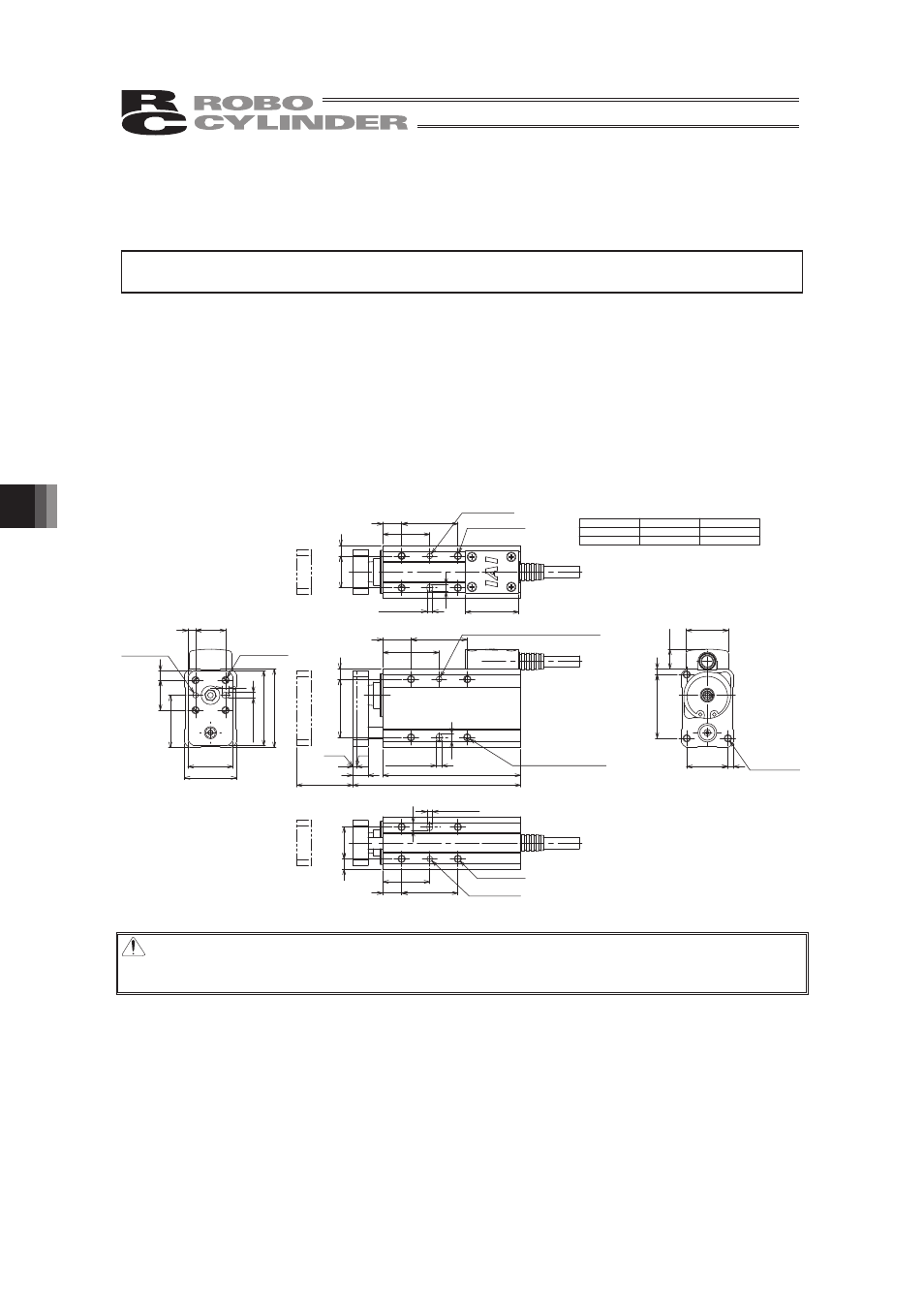
8. Installation
64
8.4
Single Guide Types
GS3NA, GS3N (Lead screw, ball screw), GS4NA, GS4N (Lead screw, ball
screw)
The actuator mounting surface should be machined or otherwise processed to a smooth surface
of equivalent precision.
• The effective depth varies depending on the actuator model and mounting surface. Determine an
appropriate length for the screws to be used by referring to the figure below.
• Circular and long positioning pin holes are provided in each mounting surface. Use these holes if
necessary.
Ɣ GS3NA, GS3N (Lead screw, ball screw)
The actuator is structured in such a way that it can be affixed on any of its four sides. The load
can be installed only one side.
ST
L1
L2
30
89.5
73.5
50
109.5
93.5
2
4
ST
30
30
15
L1
L2
8
2-φ3
depth 3 (same on opposite side)
31
5.5
2-3
depth 3
(same on opposite side)
+0.05
0
ME
10.5
22
34
22.6
3
3
4
40
24
16
16
5
4
28
42
φ
3
depth 3
+0.03
0
3
de
pt
h 3
+0.05 0
28
4
30
25
10
17
5.5
28.5
φ
3
depth 3
+0.03
0
3
depth 3
+0.05
0
4
30
25
17
5.5
10
φ
3
depth 3
+0.03
0
3
depth 3
+0.05
0
4-M4 through
8-M4, depth 4 (*)
(same on opposite side)
3-M4, depth 4
Home
4-M4, depth 4 (*)
+0.03
0
4-M4, depth 6
Caution : Some tapped mounting holes are through holes. Never use long screws exceeding
the effective thread length. Such long screws may damage the internal mechanism
or electrical parts.
(Note) Only 30mm is available for the stroke
of Slide Screw GS3N Type.