IAI America RCA2-SD4N User Manual
Page 69
8. Installation
61
[Procedure 2] Correcting the position of encoder phase Z
If the cutout groove in the shaft is outside the allowable angle range, make correction by
following the procedure below:
[1] Use a spanner to hold the width across flats on the clasp at the tip to keep it in position, and
loosen the lock nut slightly.
[2] Move the clasp at the tip slightly in the rotating direction to correct the position.
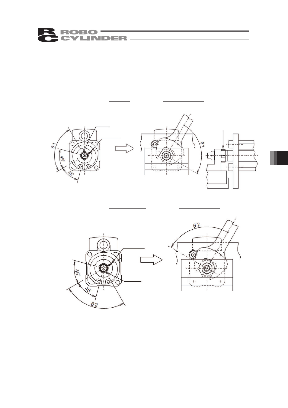
• If the cutout groove in the shaft is deviated in the A (NG) direction:
Move the clasp at the tip clockwise roughly by the correction angle T1 (as viewed from the
front).
As viewed from the front
Apply a spanner.
Marking
(orange)
Cutout groove
in shaft
• If the cutout groove in the shaft is deviated in the B (NG) direction:
Move the clasp at the tip counterclockwise roughly by the correction angle T2 (as viewed
from the front).
As viewed from the front
Marking
(orange)
Cutout groove
in shaft
[3] After the correction, tighten the lock nut with the clasp at the tip still held in position.
[Procedure 3] Confirming the phase Z position again
Finally, repeat [Procedure 1] to confirm the position of phase Z again.
If the position is inside the allowable angle, phase Z has been corrected properly.