Guide-side bracket – IAI America RCA2-SD4N User Manual
Page 62
8. Installation
54
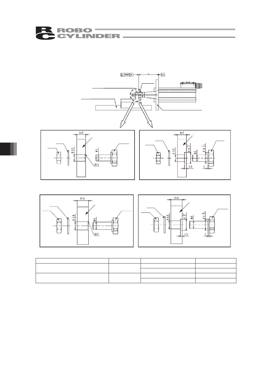
Keep the coaxiality between the actuator mounting hole in the actuator mounting hole and
tip-bracket mounting hole in the guide-side bracket, to within 0.05. Also keep the parallelism to
within 0.02.
Flat washer
Tip bracket
Guide-side bracket
M6 nut
Tip bracket
Guide-side bracket
Flat washer
M6 nut
Flat washer
Tip bracket
Guide-side bracket
M5 nut
Tip bracket
Guide-side bracket
Flat washer
M5 nut
Guide-side bracket
(Please prepare separately)
Detent guide
(Please prepare separately)
Actuator mounting plate
12 mm
(width across
flats)
RP3 Guide-side bracket (without counterbore)
RP3 Guide-side bracket (with counterbore)
RP4 Guide-side bracket (without counterbore)
RP4 Guide-side bracket (with counterbore)
Type
Lead
Guide-side bracket
L
Without counterbore
11.5 ±0.1
RP3NA, RP3N (Lead screw, ball screw)
RP4NA, RP4N (Lead screw, ball screw)
1
With counterbore
10.5 ±0.1
Without counterbore
11.8 ±0.1
RP3NA, RP3N (Lead screw, ball screw)
RP4NA, RP4N (Lead screw, ball screw)
2, 4, 6
With counterbore
10.8 ±0.1