Darex XPS-16 Operating Instructions User Manual
Page 117
User Manual Page 24
3. Securing the switch in place is a plastic nut at
the base of the threads. Use needle nose pli-
ers to remove the nut and slide the switch out.
4. Slip the new switch in place with the key to
the left or inside of the casting and the clip to
the right or wall side of the casting.
5. Secure with the plastic nut, but do not over
tighten.
6. Slide the switch block over the keyed switch,
prong side up until it snaps in place.
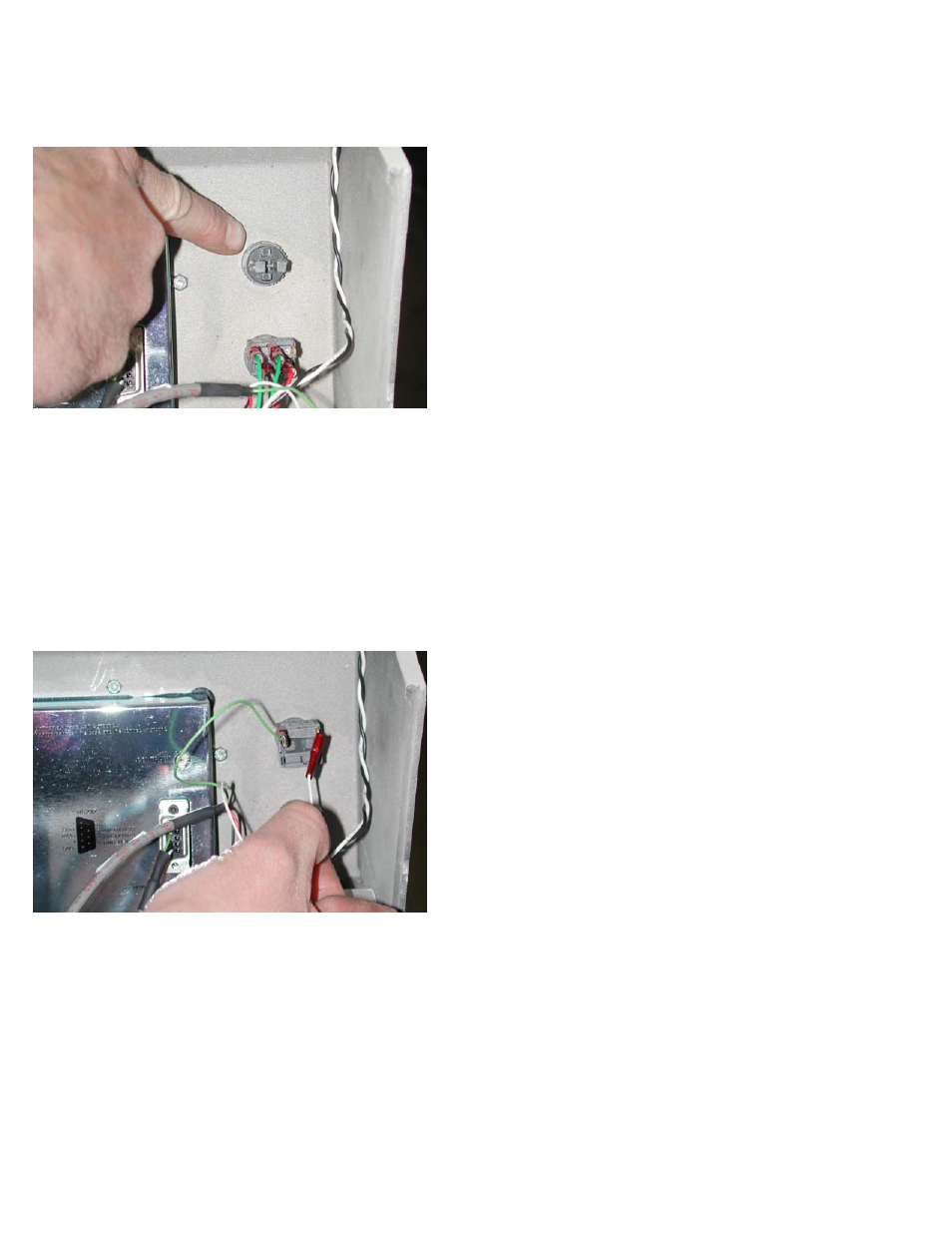
7. Connect the wires as follows. The green wire
connects to the inside prong and the white to
the wall side prong.
Cycle Start switch (green)
1. Before removing the wires, note the pattern of
connection. Two green to top inside prongs.
Black then red on the bottom inside prong.
The top outside or wall side prong is vacant.
2. Follow the same connector removal procedure
as for the E-Stop and remove all wires.
3. Though different, the switch block removes
and installs the same as the E-Stop switch.
Follow the same instructions as above.
4. Once the switch block has been removed, re-
move the plastic retainer nut, also same as E-
Stop.
5. Slide the switch from the casting, but note the
rubber gasket and locator pin that protrudes
through the gasket and locates the switch on
the top cover. It must locate in this position.
Feed Hold (amber
)
1. Follow Cycle Start switch replacement steps to
replace Feed Hold switch.