Enforce – FEC DSP1500 Main Unit User Manual
Page 84
enFORCE
DSP1500 Main Unit Hardware Manual
(Rev. 4.0)
PAGE 5 - 44
Chapter 5: Control Interfaces
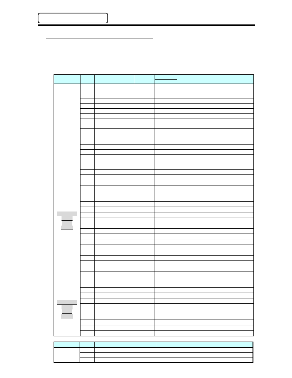
5.7.4 Ouput Signals (Word 01 ~ Word 16)
The Main Unit is capable of providing over 570 Output signals to indicate the status of the Main
Unit and of all the DSP1500 SAN Controllers connected to it (up to 31 controllers). These
signals are user configurable using the DSP User Console Software and may be programmed
on any designated bit. See Section 5.3.4 for available output signals.
Since Modbus Plus sends I/O signals 8 bits at a time, and trying to use the data as a
word, all bits and bytes are transferred backwards.
Word No.
Bit
Signal
Connection
FEC Main
Description
Bank
Bit
Output
Word
No.01
Standard
Setting
0bit
Seq/Press Output 1
NO
1
8
Echo of Seq. / Press Select 1 Input
1bit
Seq/Press Output 0
NO
1
7
Echo of Seq. / Press Select 0 Input
2bit
End
NO
1
6
Output when Press operation ends.
3bit
Busy
NO
1
5
Output while Press is operating.
4bit
Ready
NO
1
4
Output when Press operation is ready.
5bit
Abnormal
NO
1
3
Output when a Press abnormal occurs
6bit
Total Accept
NO
1
2
Output when result is a [Total Accept]
7bit
Total Reject
NO
1
1
Output when result is a [Total Reject].
8bit
Press No.1 BYP
NO
1
16 Press NO.1 is in bypass.
9bit
Press No.1 ABN.
NO
1
15 Press NO.1 is abnormal.
10bit
Press No.1 Reject
NO
1
14 Press NO.1 pressing is rejected.
11bit
Press No.1 Accept
NO
1
13 Press NO.1 pressing is accepted.
12bit Press in Bypass
NO
1
12 Output when any press is in Bypass
13bit Seq/Press Output 4
NO
1
11 Echo of Seq. / Press Select 4 Input
14bit Seq/Press Output 3
NO
1
10 Echo of Seq. / Press Select 3 Input
15bit Seq/Press Output 2
NO
1
9
Echo of Seq. / Press Select 2 Input
Output
Word
No.02
Example of
output
signal
setting
0bit
Press No.3 BYP
NO
1
24 Press NO.3 is in bypass.
1bit
Press No.3 ABN.
NO
1
23 Press NO.3 is abnormal.
2bit
Press No.3 Reject
NO
1
22 Press NO.3 pressing is rejected.
3bit
Press No.3 Accept
NO
1
21 Press NO.3 pressing is accepted.
4bit
Press No.2 BYP
NO
1
20 Press NO.2 is in bypass.
5bit
Press No.2 ABN.
NO
1
19 Press NO.2 is abnormal.
6bit
Press No.2 Reject
NO
1
18 Press NO.2 pressing is rejected.
7bit
Press No.2 Accept
NO
1
17 Press NO.2 pressing is accepted.
8bit
Press No.5 BYP
NO
1
32 Press NO.5 is in bypass.
9bit
Press No.5 ABN.
NO
1
31 Press NO.5 is abnormal.
10bit
Press No.5 Reject
NO
1
30 Press NO.5 pressing is rejected.
11bit
Press No.5 Accept
NO
1
29 Press NO.5 pressing is accepted.
12bit
Press No.4 BYP
NO
1
28 Press NO.4 is in bypass.
13bit
Press No.4 ABN.
NO
1
27 Press NO.4 is abnormal.
14bit
Press No.4 Reject
NO
1
26 Press NO.4 pressing is rejected.
15bit
Press No.4 Accept
NO
1
25 Press NO.4 pressing is accepted.
Output
Word
No.03
Example of
output
signal
setting
0bit
Press No.7 BYP
NO
2
8
Press NO.7 is in bypass.
1bit
Press No.7 ABN.
NO
2
7
Press NO.7 is abnormal.
2bit
Press No.7 Reject
NO
2
6
Press NO.7 pressing is rejected.
3bit
Press No.7 Accept
NO
2
5
Press NO.7 pressing is accepted.
4bit
Press No.6 BYP
NO
2
4
Press NO.6 is in bypass.
5bit
Press No.6 ABN.
NO
2
3
Press NO.6 is abnormal.
6bit
Press No.6 Reject
NO
2
2
Press NO.6 pressing is rejected.
7bit
Press No.6 Accept
NO
2
1
Press NO.6 pressing is accepted.
8bit
Press No.9 BYP
NO
2
16 Press NO.9 is in bypass.
9bit
Press No.9 ABN.
NO
2
15 Press NO.9 is abnormal.
10bit
Press No.9 Reject
NO
2
14 Press NO.9 pressing is rejected.
11bit
Press No.9 Accept
NO
2
13 Press NO.9 pressing is accepted.
12bit
Press No.8 BYP
NO
2
12 Press NO.8 is in bypass.
13bit
Press No.8 ABN.
NO
2
11 Press NO.8 is abnormal.
14bit
Press No.8 Reject
NO
2
10 Press NO.8 pressing is rejected.
15bit
Press No.8 Accept
NO
2
9
Press NO.8 pressing is accepted.
:
Word No.
Bit
Signal
Connection
Description
Output
Word
No.16
0bit NO
… …
15bit NO