FEC DSP1500 Main Unit User Manual
Page 26
enFORCE
DSP1500 Main Unit Hardware Manual
(Rev. 4.0)
PAGE 3 - 4
Chapter 3: System Description
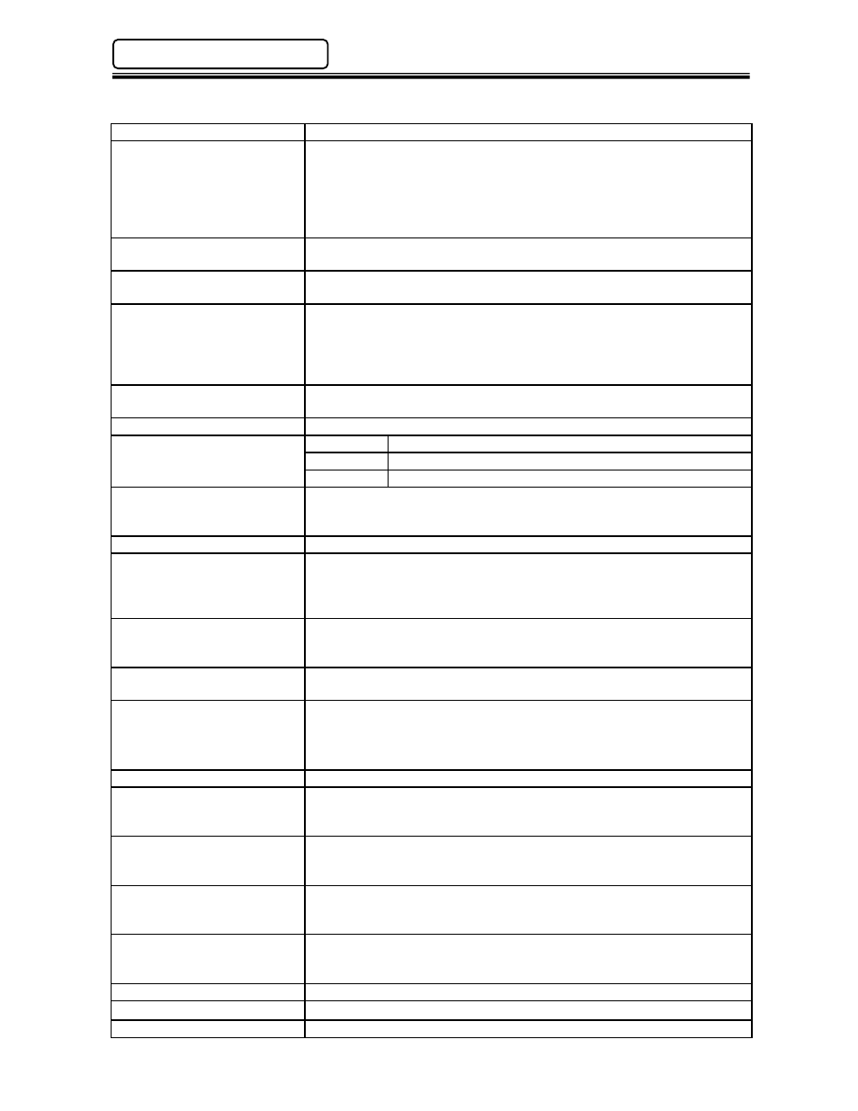
Main Unit Panel Description
Power On LED
Indicates when power is applied to the Main Unit.
Busy LED
Lights when the unit is performing a self check, Home Search, Home
Return, Sequence operation, Jog operation or is
downloading/uploading data to the DSP Software.
Blinks when clearing stored data in the Main Unit and while
communicating when “Disable Main Unit When Communicating” is
checked in the DSP Software.
Accept LED
Lights if a pressing cycle or a self check test falls within acceptable
parameters. (This LED indicates status for ALL connected presses)
Reject LED
Lights if a pressing cycle or a self check test is outside of acceptable
parameters. (This LED indicates status for ALL connected presses)
Abnormal LED
Lights when a system abnormal condition is detected in the control
system of any connected press. (Does NOT indicate a press reject).
All operations are halted and cannot be restarted until the Abnormal
condition is corrected. Can be cleared only by the Reset function. (see
DSP1500 SAN Unit Operation Manual for Abnormal Troubleshooting)
RS485 Port
RJ45 style connector used to connect to all DSP1500 Servo (SAN)
Units included in the system.
Ethernet U/C Port
Communication port for the User Console PC.
Ethernet U/C Status LEDs
Red (TX)
Transmitting
Data
Yellow 10/100
Link
Green
(RX) Receiving Data
Reset Button
Resets all signal and communication buffers to “clear” conditions.
Clears the Abnormal signal and performs the Load Transducer Zero
Level Check.
Start Button
Starts the pressing cycle. Must be maintained during complete cycle.
Home Button
If any of the connected presses have not been “Homed”, pushing this
button will cause those presses to perform a “Home Position Search”.
If Home has been set, the connected presses will move to the Home
Position.
Cal Button
Performs the Load Transducer shunt calibration test. When pressed,
the Servo (SAN) Units will display either a green accept LED or red
reject LED indicating status of the individual Calibration test.
Power Connector
Connects to incoming power: 100 to 220VAC (auto-sensing), Single
phase, 50/60 Hz.
Interface Board (I/O)
Allocation socket for input/output signal Interface boards. Options
available are Discrete I/O (Sink or Source), Interbus-S
®
, DeviceNet
®
,
Profibus
®
, CC-Link
®
(Version 1 or 2), Modbus Plus
®
, Allen Bradley
Remote I/O (Rockwell License #199906006) or Ethernet-I/P
RS232C – PC Port
Communication port for the User Console PC.
RS232C – Data Out Port #1
Communication port for pressing result data output to a serial printer.
Data output format is configured using the User Console (DSP)
Software package.
RS232C – Data Out Port
(Ethernet Version)
Communication port for pressing result data output to any external
device, i.e.: host computer, serial printer, etc. Data output format is
configured using the User Console (DSP) Software package.
RS232C – Data In Port
Communication port for ASCII data input from peripheral devices. (Ex:
bar code readers, RF tag, etc.) Allows external ASCII data to be
merged with pressing result data.
RS232C – Data Out Port #2
Communication port for pressing result data output to a host
computer. Data output format is configured using the User Console
(DSP) Software package.
RS422 – Display Port
Communication Port for an FEC Remote Display Unit
Ethernet Network Port*
for Network Connectivity (Toolsnet
®
, QDAS
®
,Custom Protocol, etc.)
Ethernet Reset Button*
for resetting the Network Ethernet Port
*On Ethernet Version only.