8 fault isolation aids, Table 8-5. fault isolation aids – Micromod Micro-DCI: 53MC5000 PLC AND PRINTER INTERFACES User Manual
Page 99
8.8 FAULT ISOLATION AIDS
Table 8-5 summarizes information provided in this section and other sections of the book that can
be referenced as an aid to fault isolation.
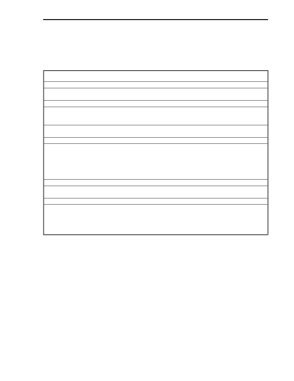
Table 8-5. Fault Isolation Aids
Environmental/Power
See Table 1-1 for RS-232/485 ITB environmental and power specifications; see 53MC5000 PCS
Instruction Bulletin for PCS environmental and power specifications.
PCS Setup Errors
Setup Errors 1 through 4 (Table 8-2) - Violating memory map restrictions. Setup Error 5 =
Memory type not 31. Setup Error 10 - Set Scan Time to non-zero value. PCS APB Setup bytes
(Table 8-1) - Should agree with the communication setup of the PLC system.
Scan Overrun Counter (Table 8-2 and Section 3.7) - Expand Scan Time if the count increases at
an unacceptable rate.
Communications
Proper cable fabrication between the RS-232/485 ITB and the PLC (Figure 8-2 or 8-3).
Communication Error and Error Count (Tables 8-3 and 8-4) - For checksum (Block Check
Character [BCC]) and bad message errors, the PCS does not use the data but will try again, for
example: if a checksum error occurs during the read, the PCS will perform the write in that Scan
Time and attempt another read the next Scan Time. If there are five consecutive read errors or
five consecutive write errors, the PCS causes a re-initialize sequence.
Possible PLC Problems
Reference the Koyo PLC documentation for possible PLC problems.
RS-232/485 ITB Activity Indicators
Inactivity from the XMT (CR13) and RCV (CR14) LEDs could indicate line problems, a hung
device, a misconfiguration between the PCS and PLC resulting from manual database alterations
made at either device, or just no DDI channel activity. Active indicators on the RS-232/485 ITB
do not necessarily mean error free operation, e.g., repeated PCS-PLC transactions attempted
with timeout errors.
Section 8. Koyo Mode
KOYO
8-7