0 printer interface, 1 purpose, 2 cable connections – Micromod Micro-DCI: 53MC5000 PLC AND PRINTER INTERFACES User Manual
Page 101: 3 ddi channel setup bytes, Table 9-1. ddi setup bytes for datalog
9.0 PRINTER INTERFACE
9.1 PURPOSE
When configured to printer interface mode, the DDI-A/B channel(s) can output serial data under
control of the resident standard format datalog program or user generated free format datalog pro-
grams executing in the Process Control Station (PCS). The standard format datalog program gen-
erates datalog printout data streams and is the only PCS resident program designed to use the
printer interface. It is assumed user generated free format datalog programs will require the printer
interface to produce datalog printouts similar to the standard format datalog program. The informa-
tion in this section is therefore presented within that context. This section contains information to
connect a printer to the PCS RS-232/485 ITB, to printout a standard datalog, and examples of free
format datalog printouts.
9.2 CABLE CONNECTIONS
The output of the DDI-A/B channel(s) is RS-485/422 serial data. In general these signals are con-
verted to RS-232 serial data by the RS-232/485 ITB. As shown in Figure 9-1, PCS J5 connects to
J5 of an ITB for the DDI-A channel output, and PCS J9 connects to J4 of an ITB for DDI-B channel
output. A user provided serial data cable is required that connects J1 of the ITB to a serial-
to-parallel converter or directly to a serial printer. Pin designators for this cable are illus-
trated in Figure 9-1. Also, if the printer has a parallel interface, then a serial-to-parallel
converter and a parallel cable must be provided by the user. The serial-to-parallel converter
should have a minimum buffer size large enough for the datalog output (e.g., the standard
datalog is 1000 characters and requires a serial-to-parallel converter with a minimum 1
Kbyte buffer).
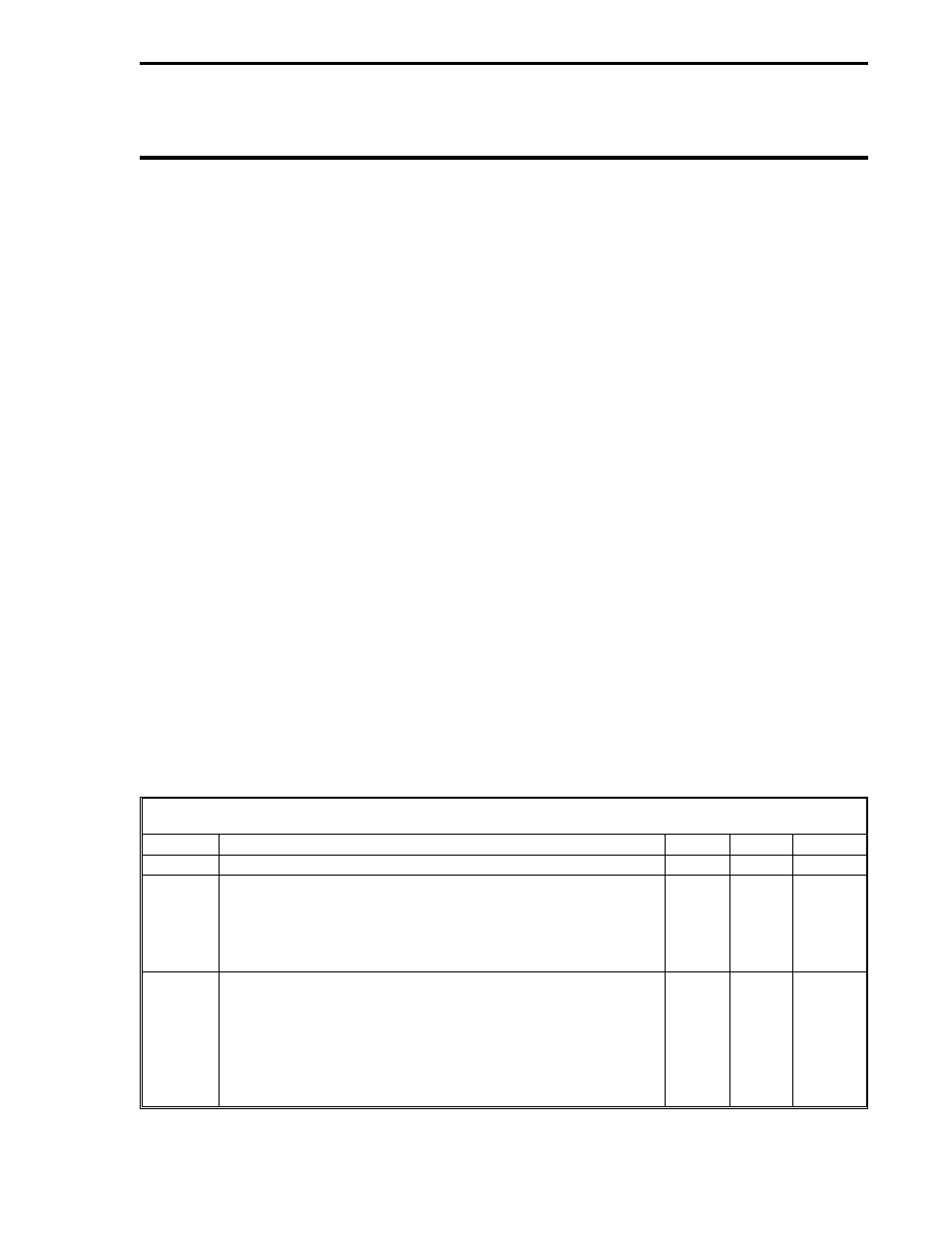
9.3 DDI CHANNEL SETUP BYTES
The printer interface is a unidirectional communications channel. As such, any device connected
to DDI-A or DDI-B when configured as a printer interface must be capable of operating at one of
the baud rates and set-up values given in Table 9-1 below without requiring dataflow control.
Table 9-1. DDI Setup Bytes for Datalog
Title
Definition
DDI-A
DDI-B
Default
Mode
0 = Off, 10 = Datalog
B290
B456
0
Baud
Rate
It designates the data transfer rate as follows:
10 = 38400 6 = 9600 2 = 600
9 = 28800 5 = 4800 1 = 300
8 = 14400 4 = 2400 0 = 110
7 = 19200 3 = 1200
B292
B458
0
Set-Up
It designates the data transfer protocol as follows:
0 = 8 bits, 1 stop bit, no parity
1 = 8 bits, 1 stop bit, even parity
2 = 8 bits, 1 stop bit, odd parity
3 = 7 bits, 1 stop bit, even parity
4 = 7 bits, 1 stop bit, odd parity
5 = 7 bits, 2 stop bits, no parity
B293
B459
0
Section 9. Printer Interface
PRINTER
9-1