Table 6-7. pcs modbus slave commands – Micromod Micro-DCI: 53MC5000 PLC AND PRINTER INTERFACES User Manual
Page 79
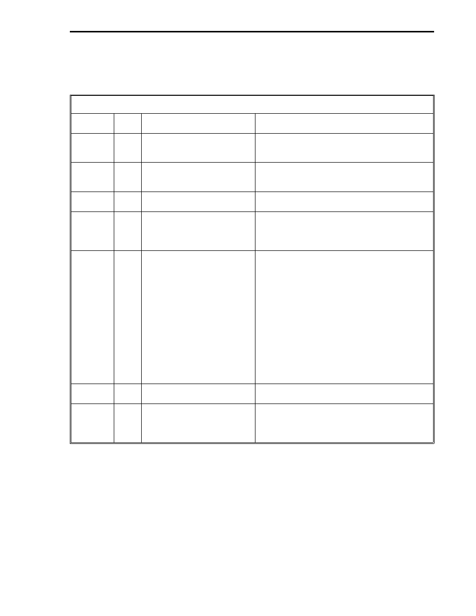
6.5.2 PCS MODBUS SLAVE COMMANDS
The commands that the PCS Modbus slave responds to are listed in Table 6-7 as follows:
Table 6-7. PCS Modbus Slave Commands
Function
Code
Data
Type
Title
Description
1
L
Read Coil Status
This command causes the PCS to respond
with consecutive variables in the range of L000
to L2047.
3
C
Read Holding Registers
This command causes the PCS to respond
with consecutive variables in the range of
C000 to C767.
5
L
Force Single Coil
(for Slave Mode only)
This command sets the value of one PCS coil
in the range of L000 to L2047.
6
C
Preset [Write] Single Holding
Register
This command sets the value of one PCS
holding register in the range of C000 to C767.
Legal values are 16 bit unsigned integers (see
Section 3.5).
8
N/A Loopback Diagnostic Test
This command is used to check the
communications link to the PCS Modbus
Slave. Four diagnostic codes are supported:
Diagnostic Code = 00, Return Query Data -
This command causes the PCS Modbus Slave
to loopback received data.
Diagnostic Code = 01, Restart Communica-
tions Option - This command clears the listen-
only mode.
Diagnostic Code = 02, Return Diagnostic
Register - This command returns zero data.
Diagnostic Code = 04, Force Listen Only Mode
This command disables outgoing responses
from the PCS Modbus Slave.
15
L
Force [Write] Multiple Coils
This command allows the state of consecutive
coils to be changed in the range of L000-L2047.
16
C
Preset [Write] Multiple
Registers
This command allows the values of consecu-
tive holding registers to be changed in the
range of C000 to C767. Legal values are 16
bit unsigned integers (see Section 3.5).
Section 6. MODBUS RTU Mode
MODBUS2
6-15