Table 4-6. kf3 setup selections, 1 of 2 – Micromod Micro-DCI: 53MC5000 PLC AND PRINTER INTERFACES User Manual
Page 42
PLC Control and Status Bytes (Table 4-3)
Scan Time (B685, B661) - See Section 3.7 to calculate the Scan Time.
PLC Read Control Bytes (Table 4-4)
PLC Address (B664, B640) - This is a decimal value of the PLC address.
Starting PLC Memory Address High and Low Bytes (B665, B641, B666, B642) - Also,
see Section 3.4 to ensure these values are properly calculated.
Number of L-Words to Read (B667, B643) - Can not exceed 32.
Number of C-Words to Read (B668, B644) - Can not exceed 64.
Destination Address (B669, B645) - For PLC networks; it is the network interface
address used by the initialization message.
PLC Write Control Bytes (Table 4-5)
PLC Address (B674, B650) - This is a decimal value of the PLC address.
Starting PLC Memory Address High and Low Bytes (B675, B651, B676, B652) - Also,
see Section 3.4 to ensure these values are properly calculated.
Number of L-Words to Write (B677, B653) - Can not exceed 32.
Number of C-Words to Write (B678, B654) - Can not exceed 64.
Write Command (B679, B655) - 0 for Protected Writes, 8 for Unprotected Writes.
APB Setup Bytes (Table 4-2)
Mode (B290, B456) - 1 to start Allen-Bradley PLC interface protocol.
RS-232/485 ITB
XMT (CR13) and RCV (CR14) LEDs alternately blink whenever there is PCS-PLC
activity.
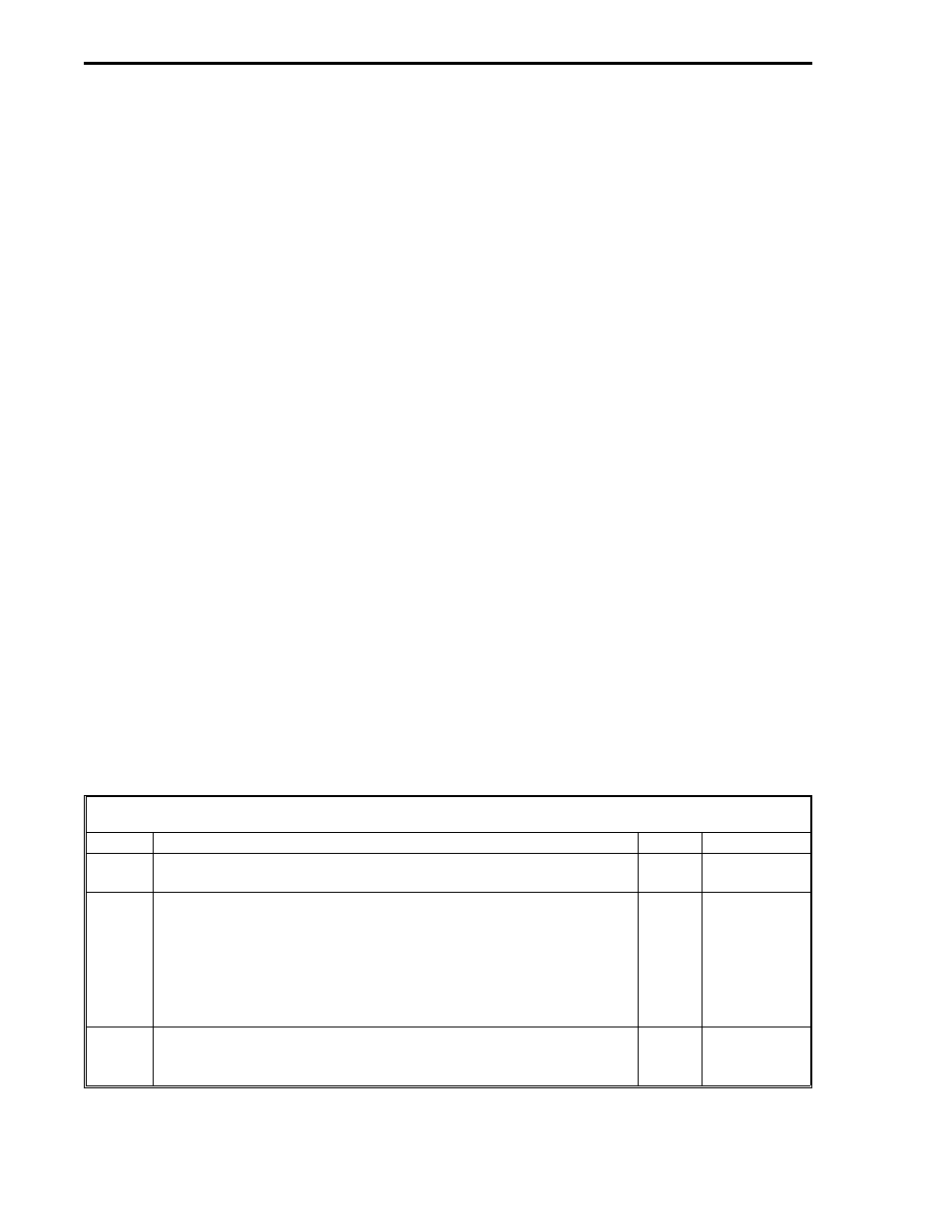
4.7.1 ALLEN-BRADLEY KF3 SETUP SELECTIONS
The selections for a typical KF3 unit are summarized in Table 4-6. It is recommended these same selections
be used whenever possible. Reference the Allen-Bradley KF3
documentation for information regarding the setup selections.
Table 4-6. KF3 Setup Selections
Option
Description
Range
Set Value
0
Node Address (Choose an address number that is not already
dedicated to another network device.)
0-31
Any valid
address 0-31
1
DH-485 Baud Rate
300
1200
2400
4800
9600
19200
03
12
24
48
96
19
96
2
Diagnostic Command Execution
No
Yes
00
01
00
1 of 2
53MC9015 53MC5000 PLC and Printer Interfaces
4-8
ALLEN