Table 7-3. siemens plc read control bytes, 1 of 2 – Micromod Micro-DCI: 53MC5000 PLC AND PRINTER INTERFACES User Manual
Page 88
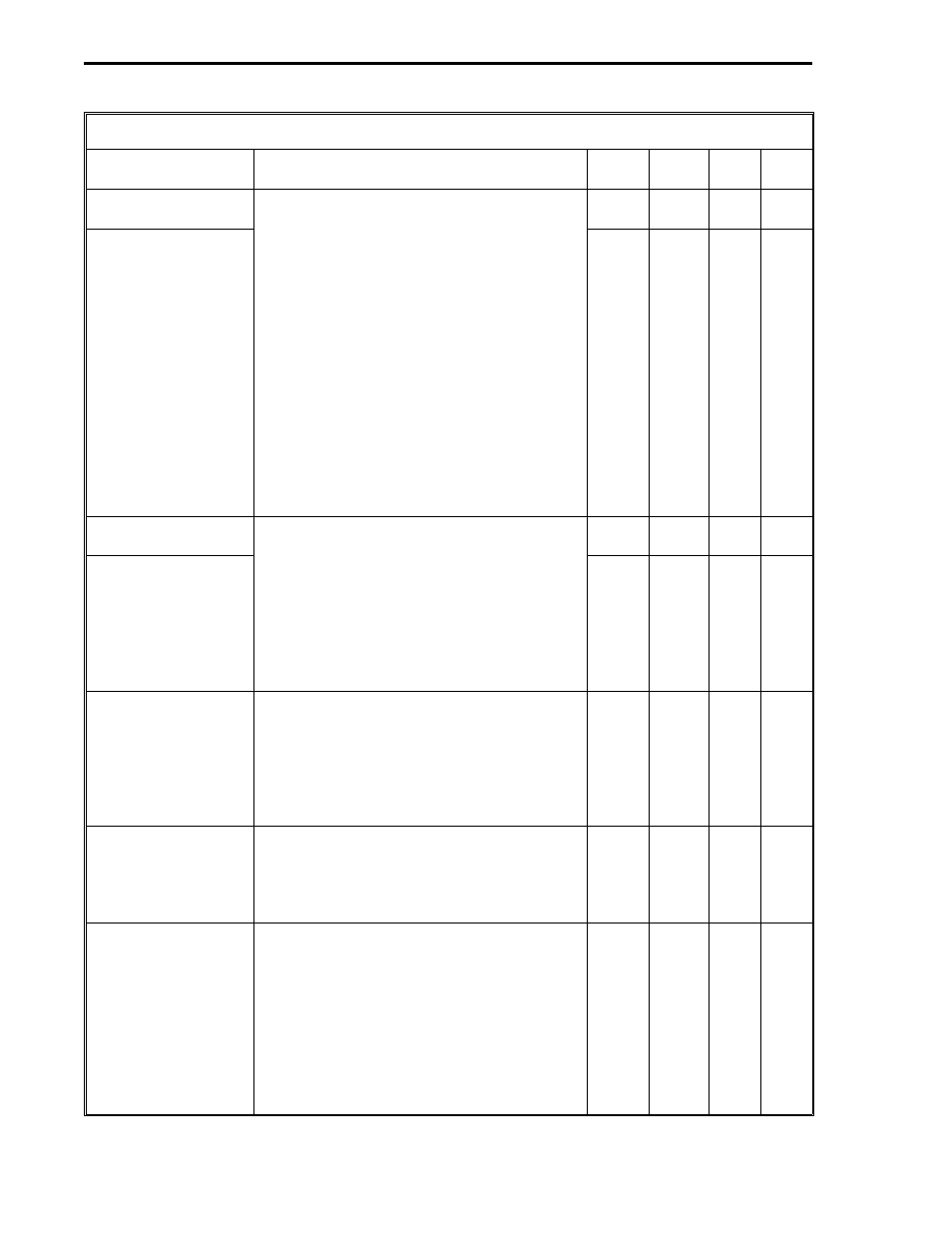
Table 7-3. Siemens PLC Read Control Bytes
Title
Definition
DDI-A DDI-B
Set
By
De-
fault
Starting PLC Memory
Address (Low)
The two byte PLC memory starting address.
For Command 1, the low byte is the Data
Word (DW) number and the high byte is the
Data Block (DB) number. For commands 2-
6, the high and low bytes form a 16 bit
unsigned binary integer. For command 2, it
is a PLC memory address. For commands
3-6, it is the number of the selected entity
(e.g., input byte 3 or flag byte 32). An
example of both bytes functioning together
as a 16 bit unsigned binary integer is as
follows: the PLC hexadecimal address
4180
16
is entered as 65
10
in the high byte
B666 [or B642] and 128
10
in the low byte
B665 [or B641] because each byte requires
a decimal number. (See Appendix A for
decimal conversions.)
B665
B641
User
0
Starting PLC Memory
Address (High)
B666
B642
User
0
Number of L-Bytes to
Read
Count must not exceed 128 bytes total. For
command codes 1 and 2, maximum count
is: L = 64 bytes (512 contacts) and C = 32
words, or L = 0 bytes and C = 64 words.
For command code 3, maximum count is L
= 0 bytes and C = 64 words. For command
codes 4 - 6, maximum count is: L = 64
bytes (512 contacts) and C words are not
applicable.
B667
B643
User
0
Number of C-Words
to Read
B668
B644
User
0
Command Code
It is the read command code as follows:
1 = D: DataBlock (word, L & C)
2 = S: Absolute Address (word, L & C)
3 = Z: Counter Locations (word, C only)
4 = E: Input Bytes (byte, L only)
5 = A: Output Bytes (byte, L only)
6 = M: Flag Bytes (byte, L only)
B669
B645
User
0
PLC Error Code*
The PLC Error Codes are reported in
decimal; however, they are listed in
hexadecimal in the PLC manual. See the
Siemens PLC manual for the error code
definitions.
B671
B647
N/A
N/A
Communications
Error Code*
0 = no errors. 255 = timeout error - a
timeout error indicates no response came
back from the PLC. 254 = bad checksum
(CRC) - a bad checksum indicates even
though the frame was formatted properly,
the data can not be used. 253 = bad
message - bad message indicates that
errors were found in the predictable portion
of the message from the PLC. 252 and 251
= PCS hardware malfunction.
B672
B648
Soft-
ware
0
1 of 2
53MC9015 53MC5000 PLC and Printer Interfaces
7-4
SIEMENS