2 of 2 – Micromod Micro-DCI: 53MC5000 PLC AND PRINTER INTERFACES User Manual
Page 76
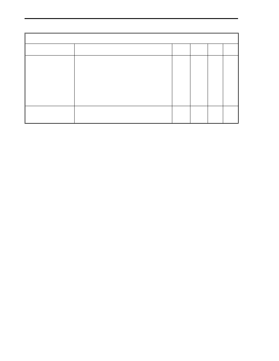
Table 6-5. Write Control Bytes for PCS Modbus Master
Title
Definition
DDI-A DDI-B
Set
By
De-
fault
Communications
Error*
0 = no errors. 255 = timeout error - a
timeout error indicates no response came
back from the PLC. 254 = bad checksum
(CRC) - a checksum indicates even though
the frame was formatted properly, the data
can not be used. 253 = bad message - bad
message indicates unexpected data was
found in the reply from the PLC. 252 and
251 = PCS hardware malfunction.
B682
B658
Soft-
ware
0
Error Count*
This byte is a running total of the Exception
Response Codes and the Communication
Errors listed above.
B683
B659
Soft-
ware
0
*User can reset by writing zeros into the datapoints.
6.4.15 PCS MODBUS MASTER SET-UP PROCEDURE
The Modbus PLC documentation must be referenced to install and configure the PLC.
1. Reference the 53MC5000 Process Control Station book listed in the Preface to install the PCS.
2. See Section 2 of this book to mount the RS-232/485 ITB and cable connect it to the PCS.
3. This section provides an illustration of the required custom RS-232 cable if J1 of the ITB is to
be connected to the PLC; otherwise, the standard RS-485 four wire bundle can be used if TB2
is to be connected to the PLC.
4. See Section 2 of this book for the required power connections to the RS-232/485 ITB.
5. Define the PLC memory map as determined from the quantity of L-bytes and C-words to be
transferred between the PCS and PLC. The size and address locations of the PCS L- and C-
memory areas are defined in Section 3.1 and illustrated in Figures 3-1 and 3-2.
6. At the PCS, configure all of the appropriate DDI channel datapoints set by the user as follows:
PCS APB Setup Bytes (Table 6-2)
Mode (B290, B456) - 0 (to ensure interface is off.)
Baud Rate (B292, B458) - Set to match the PLC.
Set-Up (B293, B459) - Data format transfer protocol is set to match the PLC.
PLC Control and Status Bytes (Table 6-3)
Scan Time (B685, B661) - See Section 3.7 to calculate the Scan Time.
PLC Read Control Bytes (Table 6-4)
PLC Address (B664, B640) - This is a decimal value of the PLC address.
Starting PLC Memory Address Low and High Bytes (B665, B641, B666, B642) - Also,
see Section 3.4 to ensure these values are properly calculated.
Number of L-bytes to Read (B667, B643) - Can not exceed 64.
Number of C-words to Read (B668, B644) - Can not exceed 64.
2 of 2
53MC9015 53MC5000 PLC and Printer Interfaces
6-12
MODBUS2